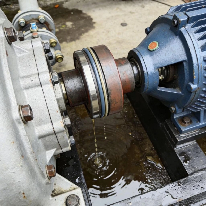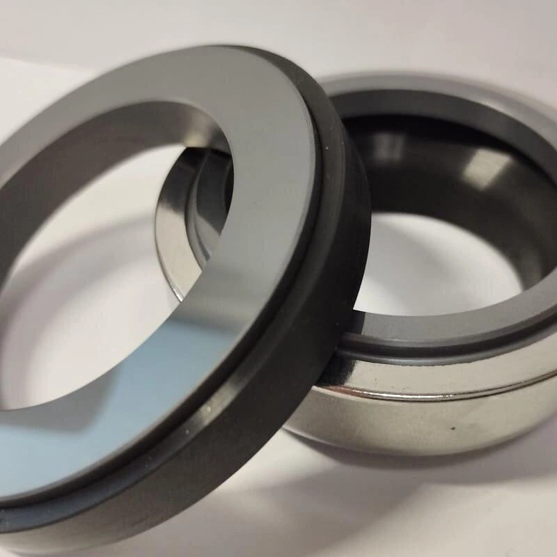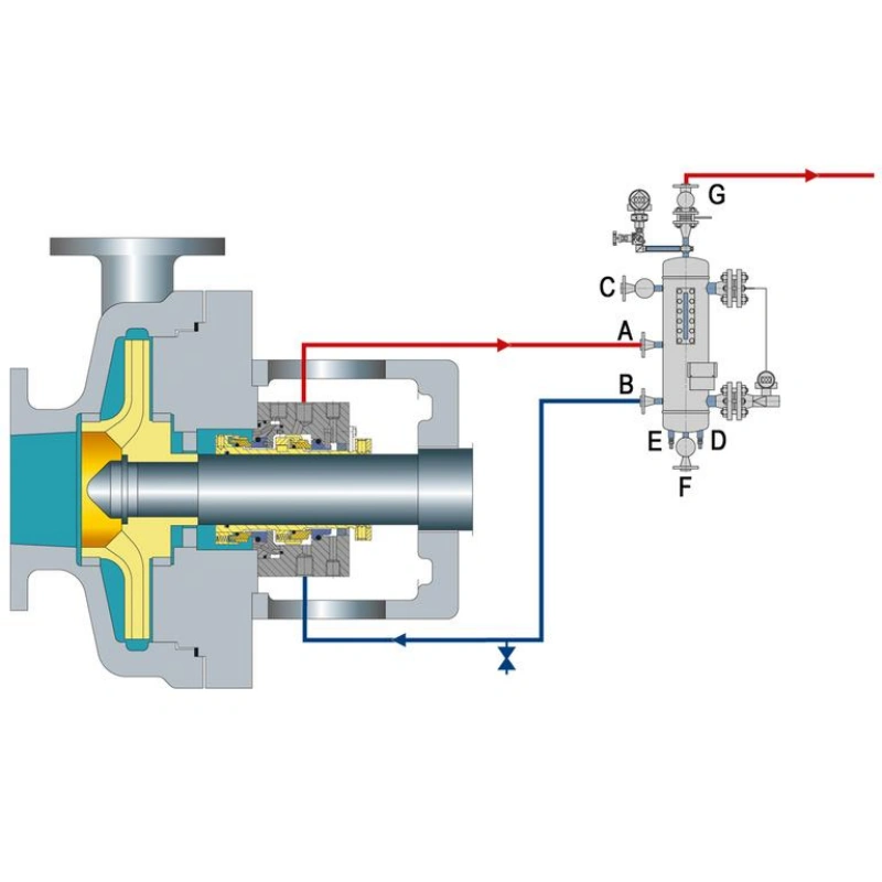

Both Pusher and Non-Pusher seals rely on face-to-face contact to prevent leakage, but there are significant differences in terms of auxiliary sealing, axial compensation, temperature resistance, and reliability.
When selecting a seal, don’t focus solely on the purchase price or equipment model—what truly determines seal life are the on-site operating conditions: temperature, pressure, media corrosiveness, shaft sleeve condition, vibration, and axial runout.
Next, we’ll clarify the application limits of these two seal types by examining several key aspects: operating principles, structural differences, a comparison between dynamic O-rings and metal bellows, temperature and chemical compatibility, pressure capacity, and common failure modes.
A pusher mechanical seal is a type of mechanical seal that uses a spring to provide axial compensation and a dynamic O-ring to achieve auxiliary sealing.
Its key feature is that when the sealing faces wear down or the equipment experiences a certain amount of axial displacement, the moving seal ring can move axially; the spring then pushes it to maintain contact with the stationary seal ring, thereby sustaining the seal.
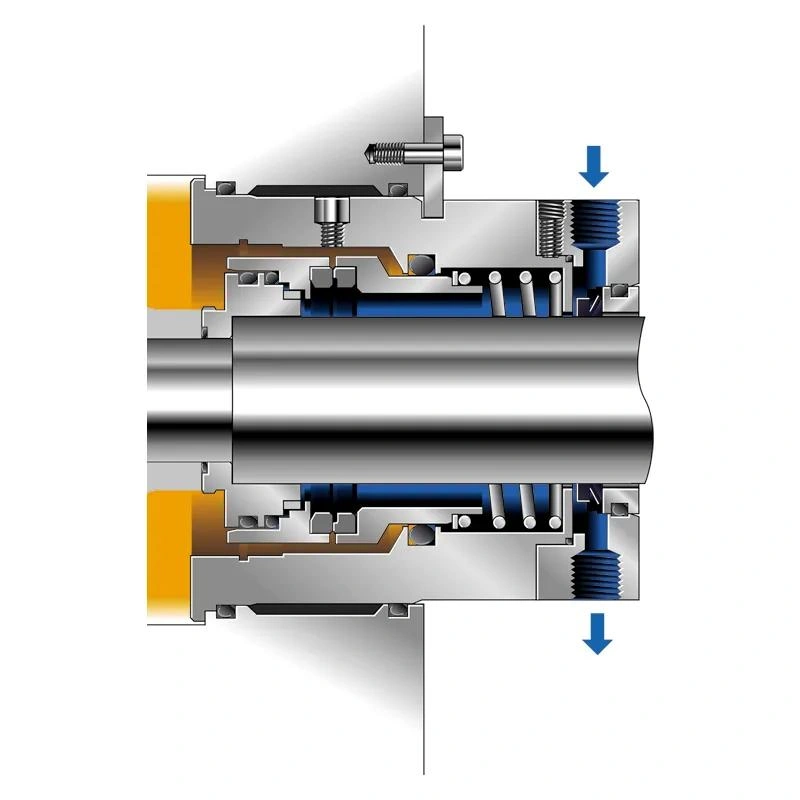
Rotating Seal Ring: Mounted on the shaft or shaft sleeve, it rotates with the shaft; its end face contacts the stationary ring to form the primary sealing interface.
Stationary Seal Ring: Fixed in the gland and non-rotating, it mates with the rotating ring and controls leakage through a precision-fit end face.
Spring: Provides initial axial preload and, in the event of end face wear or shaft runout, pushes the moving assembly to compensate, maintaining end face contact.
Dynamic O-ring: A key auxiliary seal for the Pusher, installed between the moving assembly and the sleeve; it slides along the sleeve surface to provide auxiliary sealing and axial compensation.
Seal gland: Secures the stationary ring assembly and mounts the entire sealing assembly to the pump body or seal chamber.
After the mechanical seal is installed, the spring applies axial thrust to the moving seal ring, keeping the rotating seal ring in contact with the stationary seal ring.
This preload establishes a basic sealing condition before the equipment is started, reducing the likelihood of media leakage through the sealing faces.
Tip: The spring is not the only source of closing force. Once the equipment is running, the pressure of the medium within the seal chamber also affects the force conditions on the sealing faces.
When the pump begins to operate, the rotating seal ring rotates with the shaft, while the stationary seal ring remains stationary.
A very thin fluid film forms between the two sealing faces. This liquid film reduces direct friction between the faces while helping to control medium leakage.
During long-term operation, normal wear occurs on the faces of the rotating and stationary rings. At this point, the spring pushes the moving seal assembly to move axially, causing the two faces to re-engage and thereby achieving automatic compensation.
The dynamic O-ring not only provides auxiliary sealing but also directly affects the axial compensation capability of the Pusher Mechanical Seal.
You can think of it as an elastic seal that both seals and allows the moving components to slide.
During normal operation, it must simultaneously meet two requirements:
The Pusher design is well-established with a clear compensation mechanism; its O-ring and spring system is easy to maintain, and spare parts are readily available.
General-purpose industrial pumps: For mild media such as clean water, circulating water, and general industrial water—where pressure and temperature are not high—the Pusher is a common and economical choice.
General-purpose chemical pumps: When the medium is compatible with the O-ring material and does not contain large amounts of particles or substances prone to crystallization, this design can be used for the transfer of various chemical liquids.
Conventional industrial rotating equipment: When operating parameters are within the design range, the shaft sleeve is in good condition, and vibration and axial play are controllable, the spring can reliably compensate for face wear.

A non-pusher mechanical seal is a type of mechanical seal that utilizes the elastic deformation of a bellows to provide axial compensation and auxiliary sealing.
Rotating Seal Ring: Mounted on the shaft or shaft sleeve, it rotates with the shaft; its end face contacts the stationary seal ring to form the primary sealing interface.
Stationary Seal Ring: Fixed in the gland and non-rotating, it works in conjunction with the rotating seal ring to prevent leakage at the end face.
Metal Bellows: The core component of the Non-Pusher design, consisting of multiple layers of formed metal bellows stacked together. It serves a dual function as both an elastic element and an auxiliary seal, achieving compensation through its own axial deformation.
Static Auxiliary Seal: Used exclusively at the junction between the bellows and other components; options include O-rings or graphite rings, selected based on temperature and media compatibility; it does not perform dynamic functions involving sliding along the sleeve.
Seal Gland and Sleeve: The gland secures the stationary ring assembly and mounts it to the pump body, while the sleeve positions the rotating ring assembly and protects the pump shaft surface.
The core principle of a bellows seal is to use the elastic deformation of the bellows to replace the axial sliding compensation provided by the “spring + dynamic O-ring” combination in a pusher-type seal.
Elastic Compensation: The bellows possess inherent elasticity, continuously pushing the rotating ring toward the stationary ring. It compensates for wear and shaft runout through its own compression and expansion, eliminating the need for an O-ring to slide along the sleeve.
Pressure Superposition: The pressure within the chamber acts on the effective area of the bellows, working in conjunction with the elastic force to maintain the specific contact pressure at the sealing face.
Fluid Film Lubrication: During operation, an extremely thin fluid film forms on the sealing faces, providing lubrication and dissipating heat; instability of the fluid film or flash vaporization can accelerate damage.
Primarily Static Sealing: The connections at both ends of the bellows serve as static sealing points, eliminating the dynamic O-ring sticking and sleeve wear issues commonly associated with pusher-type seals.

The key difference between pusher mechanical seals and non-pusher mechanical seals lies in their different methods of axial compensation and auxiliary sealing structures.
| Comparison | Pusher Mechanical Seal | Non-Pusher Bellows Seal |
|---|---|---|
| Basic Structure | Spring, movable seal ring, dynamic O-ring. | Metal bellows, movable seal ring, static secondary seals. |
| Axial Compensation | Sliding movement of the dynamic O-ring. | Elastic deformation of the bellows. |
| Loading Force | Usually provided by separate springs. | Usually provided by the bellows itself. |
| Secondary Sealing | Dynamic O-ring. | Bellows and static seals. |
| Dynamic O-Ring | Required. | Not required. |
| Shaft Surface | Requires a suitable sliding surface for the dynamic O-ring. | No dynamic O-ring sliding along the shaft. |
| High-Temperature Capability | Limited by O-ring material and other components. | Metal bellows offer an advantage, but static seals remain a limitation. |
| Chemical Compatibility | Focus on O-ring chemical resistance. | Focus on bellows alloy and static seal materials. |
| Deposit Effects | Deposits may cause dynamic O-ring sticking. | Particles may accumulate in bellows convolutions. |
| Axial Wear Compensation | Sliding movement of the seal assembly. | Elastic deformation of the bellows. |
| Fretting Risk | Dynamic O-ring movement may wear the shaft sleeve. | Reduces fretting caused by dynamic O-ring movement. |
| Main Failure Risks | O-ring sticking, swelling, hardening, and wear. | Bellows fatigue, corrosion, deformation, and cracking. |
| Pressure Capability | Various designs; balanced versions handle different pressure ranges. | Limited by bellows strength, stability, and design. |
| Maintenance | Inspect O-rings and sliding surfaces. | Inspect bellows integrity and fatigue condition. |
| Manufacturing & Cost | Established designs with wider standard product availability. | Higher material and manufacturing requirements; more customization. |
| Typical Applications | General industrial water pumps and chemical pumps. | High-temperature pumps, chemical pumps, and services unsuitable for dynamic O-rings. |
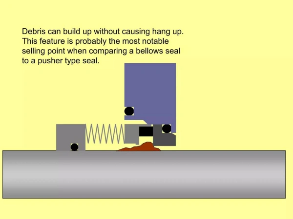
In mechanical seals, both the dynamic O-ring and the bellows are critical components that affect sealing reliability. Not only do they serve as auxiliary seals, but they also directly determine how the moving sealing assembly accommodates axial movement.
A dynamic O-ring is installed between the moving sealing assembly and the shaft/sleeve to provide a seal while allowing axial sliding. It primarily serves two functions:
Auxiliary sealing: It prevents the medium from leaking around the gap between the moving ring and the sleeve by forming a sealing contact through elastic compression.
Axial Movement: As the sealing faces wear, the moving component must compensate axially to maintain contact; the dynamic O-ring allows for this sliding while maintaining the seal.
Tip: Friction exists between the O-ring and the sleeve. If the friction is too high, the moving component may be unable to compensate in a timely manner, resulting in insufficient sealing face contact and an increased risk of leakage.
The bellows is the core component of the Non-Pusher; it combines the functions of the “spring + dynamic O-ring” assembly found in the Pusher.
Axial Compensation: When end-face wear occurs or the shaft moves axially, the bellows uses its own elastic deformation to push the compensation ring forward, maintaining end-face contact without requiring the ring to slide along the sleeve.
Auxiliary Sealing: The bellows forms a continuous metal sealing boundary, preventing the medium from bypassing the moving ring and the shaft; the connection points at both ends serve as static sealing points.
Elastic Loading: When compressed, the bellows generates a restoring force that provides a closing force to the sealing faces, partially or fully replacing the function of a spring.
Tip: The compensating force and stiffness of a bellows are determined by its structure, material, and design parameters; not all bellows provide the same compensating force, so selection must be based on a calculation according to the operating conditions.
| Comparison | Dynamic O-Ring | Metal Bellows |
|---|---|---|
| Main Structure | Elastic rubber sealing ring. | Metal bellows structure. |
| Axial Compensation | Slides along the mating surface. | Uses its own elastic deformation. |
| Secondary Sealing | O-ring contacts the mating surface. | Bellows provide a continuous sealing boundary. |
| Sliding Interface | Present. | No dynamic O-ring sliding interface. |
| Friction | May generate sliding friction. | Mainly involves bellows deformation stress. |
| Sticking Risk | O-ring sticking may occur. | Reduces dynamic O-ring sticking risk. |
| Fretting Wear | May wear the shaft sleeve contact area. | Reduces this type of wear. |
| High-Temperature Capability | Limited by elastomer material. | Generally offers better temperature resistance. |
| Chemical Compatibility | Depends on elastomer material. | Depends on metal alloy and static seals. |
| Main Failure Risks | Swelling, hardening, wear, extrusion, and sticking. | Fatigue, corrosion, cracking, and deformation. |
| Maintenance Focus | O-ring condition and sliding surfaces. | Bellows integrity and operating travel. |
| Typical Applications | General industrial pumps and standard chemical pumps. | High-temperature pumps and specialized chemical services. |

When selecting between pusher mechanical seals and non-pusher bellows seals, temperature and chemical compatibility are two very important factors to consider.
The main difference between the two designs lies in the auxiliary sealing method.
The temperature resistance of Pusher mechanical seals is primarily determined by the material of the dynamic O-ring. When temperatures are inappropriate, three main types of problems typically arise:
Thermal aging: After prolonged exposure to heat, the rubber molecular chains cross-link or break, causing the O-ring to gradually harden and crack, thereby losing its original sealing performance.
Reduced elasticity: High temperatures exacerbate compression set, causing the O-ring’s ability to rebound to deteriorate. Even when depressurized, it struggles to return to its original shape, resulting in a corresponding decline in auxiliary sealing force.
Swelling and hardening: High temperatures accelerate the interaction between the medium and the rubber. Certain media cause the O-ring to swell, increasing its dimensions and raising sliding resistance; others lead to hardening, brittle cracking, or even seizing.
Metal bellows seals offer certain advantages under high-temperature conditions, as they do not rely on dynamic rubber O-rings sliding along the sleeve to provide axial compensation.
However, it is important to note that metal bellows are not immune to the effects of temperature.
Thermal Expansion: Differences in the coefficients of thermal expansion among components can alter internal dimensional relationships and axial operating positions.
Material Strength: High temperatures may reduce the strength and elasticity of metals, directly affecting the bellows’ load-bearing capacity and auxiliary sealing function.
Thermal Fatigue: Frequent start-stop cycles or repeated temperature fluctuations can generate cyclic thermal stresses, increasing the risk of fatigue damage; the amplitude and rate of temperature change must be comprehensively evaluated.
Static Sealing Limitations: Although there are no dynamic O-rings, the static O-rings or graphite components at the connection points are still subject to the material’s temperature resistance limits.
Chemical compatibility refers to the ability of sealing materials to maintain sufficient physical and chemical stability when in contact with the conveyed medium.
Common materials used for O-rings in mechanical seals include NBR, EPDM, FKM, and FFKM.
| Material | Main Features | Chemical Compatibility Considerations |
|---|---|---|
| NBR | Good compatibility with many mineral and lubricating oils. | Unsuitable for some strong oxidizers, solvents, and high-temperature fluids. |
| EPDM | Suitable for many water, hot-water, and chemical applications. | Generally unsuitable for mineral oils and many hydrocarbons. |
| FKM | Good resistance to many oils, fuels, and chemicals. | Limited compatibility with some amines, ketones, hot water, and steam. |
| FFKM | Good resistance to many aggressive chemicals. | High cost and not universally compatible with all chemicals. |
| Metal Material | Main Features | Selection Notes |
|---|---|---|
| 316L Stainless Steel | Good general corrosion resistance. | Limited resistance to chloride pitting and some aggressive environments. |
| Alloy 625 | Nickel-based alloy with good corrosion and high-temperature resistance. | Verify compatibility with the specific fluid, temperature, and concentration. |
| Hastelloy C-276 | Good resistance to many aggressive corrosive fluids. | Not universally compatible with all acids, alkalis, or oxidizers. |
| Selection Factor | Pusher Seal (Dynamic O-Ring) | Non-Pusher Seal (Metal Bellows) |
|---|---|---|
| High-Temperature Capability | Limited by dynamic elastomer materials. | Generally offers better performance. |
| Low-Temperature Capability | Check rubber hardening and loss of elasticity. | Check metal performance and static seals. |
| Long-Term High-Temperature Service | Check thermal aging and compression set. | Check material strength, elasticity, and thermal fatigue. |
| Strong Acids | Depends on the specific O-ring material. | Depends on bellows alloy and static seal materials. |
| Strong Alkalis | Verify elastomer formulation. | Verify alloy and secondary seal compatibility. |
| Oils | Compatible NBR or FKM grades can be selected. | Check alloy and static seal compatibility. |
| Solvents | Check swelling and chemical degradation. | Check metal corrosion and static seal compatibility. |
| Chloride-Containing Fluids | Check elastomers and other wetted materials. | Pay attention to pitting and stress corrosion risks. |
| Main Material Risks | Swelling, hardening, cracking, and loss of elasticity. | Corrosion, fatigue, deformation, and cracking. |
Work-related stress can affect the force balance on the sealing faces, the deformation of the bellows, and the reliability of the auxiliary seals. Meanwhile, the surface condition of the shaft affects the sliding of the dynamic O-ring, its sealing compensation capability, and long-term operational stability.
The pressure adaptability of Pusher mechanical seals primarily depends on the seal structure, the design of forces acting on the sealing faces, auxiliary seals, and materials.
The key factor is the balance ratio—that is, the ratio of the effective hydraulic area subjected to pressure in the seal chamber to the area of the sealing faces. Based on this, they are classified into two categories:
Unbalanced: The effective pressure area is large; an increase in pressure significantly raises the end-face closing load, leading to increased friction, accelerated temperature rise, damage to the fluid film, and accelerated wear.
Balanced: Structural optimization reduces the effective pressure area, lowering the net closing load and thereby reducing friction and heat generation; this design is more suitable for high-pressure operating conditions.
In bellows seals, the bellows serve both as an auxiliary seal and as an elastic loading element; pressure directly affects its deformation, stability, and fatigue life:
Deformation: Pressure alters axial stress and deformation; overpressure can easily cause abnormal deformation, weaken the loading force, and result in poor face-to-face contact.
Stability: Excessive pressure or design mismatches may trigger local instability, bellows collapse, or structural damage; the risk depends on the material, wall thickness, geometry, and direction of pressure.
Fatigue: Pressure fluctuations, frequent start-stop cycles, and axial vibration introduce cyclic loads, which may lead to cracks or even leaks over time.
The core of a push-ring seal lies in the dynamic O-ring sliding along the surface of the sleeve; therefore, the surface condition of the sleeve directly determines the service life and reliability of the auxiliary seal:
Surface roughness: Excessive roughness increases friction and damages the O-ring; scratches or grooves can create leakage paths, so the surface must meet the manufacturer’s specifications.
Surface hardness: Insufficient hardness leads to long-term wear and alters the O-ring’s fit conditions; for equipment requiring long-term operation or frequent maintenance, it is recommended to evaluate the sleeve material or surface treatment.
Corrosion and damage: Pitting, rust, or scratches can compromise the contact condition, increasing the risk of leakage and seizure; inspections must not rely solely on dimensional checks but must include visual or non-destructive testing of the contact areas.
Sleeve Fit: Eccentric installation, looseness, or deformation directly affects O-ring contact; verify the sleeve dimensions, concentricity, and installation quality.
Although bellows seals lack the sliding surfaces found in dynamic O-rings and place fewer demands on the shaft sleeve, the condition of the shaft remains critical to service life:

When comparing push-ring and non-push-ring bellows seals, special attention should be paid to the following three failure modes:
A failure mode specific to push-ring seals. Excessive resistance prevents the moving components from moving axially, and the spring thrust cannot compensate for end-face wear. Common causes include crystallization and deposition of the medium, O-ring swelling, damage to the sleeve surface, and high-temperature hardening.
A typical failure mode for push-ring-type seals. Under continuous contact pressure, the O-ring and sleeve undergo repeated minute relative movements, resulting in localized wear. Consequences include the formation of grooves in the sleeve, induced leakage, increased sliding resistance, and exacerbated hang-up; in severe cases, the sleeve must be replaced.
A risk specific to non-thrust ring designs. The bellows develop fatigue damage or even cracks under cyclic loading. Major contributing factors include excessive axial displacement, vibration, pressure fluctuations, thermal cycling, and media corrosion.
| Comparison | Hang-Up | Fretting | Bellows Fatigue |
|---|---|---|---|
| Seal Type | Pusher Seal | Pusher Seal | Non-Pusher Metal Bellows Seal |
| Main Components | Dynamic O-ring and movable assembly. | Shaft, sleeve, and contact surfaces. | Metal bellows and welded areas. |
| Main Causes | Deposits, swelling, or excessive friction. | Repeated small relative movements. | Repeated deformation or cyclic loading. |
| Typical Effects | Loss of axial compensation. | Wear marks or grooves on contact surfaces. | Bellows cracking or rupture. |
| Potential Leakage Mechanism | Seal faces fail to maintain proper contact. | Secondary seal damage or restricted movement. | Damage to the bellows sealing boundary. |
| Prevention | Ensure material compatibility and control deposits. | Inspect shaft sleeve condition and equipment vibration. | Control axial movement, vibration, and pressure fluctuations. |
| Key Selection Focus | Ensure smooth dynamic O-ring movement. | Maintain long-term contact surface integrity. | Verify bellows fatigue resistance under cyclic loads. |
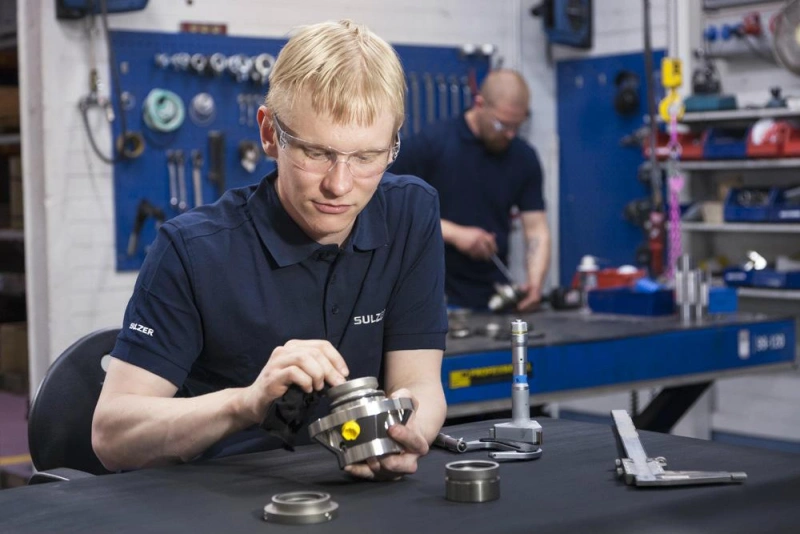
When choosing between a pusher mechanical seal and a non-pusher bellows seal, the purchase price, ease of maintenance, and availability of replacement parts will all influence your final decision.
Pusher mechanical seals offer certain cost advantages in many conventional industrial applications, primarily due to their mature design and high degree of component standardization.
A pusher seal consists of a rotating seal ring, a stationary seal ring, a spring, a dynamic O-ring, and metal support components. These components are manufactured using well-established processes, and some commonly used sizes can be purchased directly from suppliers.
| Cost Factor | Pusher Seal | Non-Pusher Bellows Seal |
|---|---|---|
| Basic Structure | Generally well-established. | May involve more complex design and manufacturing. |
| Standardization | Widely available in standard sizes. | Depends on the product range. |
| Main Components | Springs, O-rings, and seal rings. | Bellows, seal rings, and static secondary seals. |
| Special Material Costs | May increase with special elastomers and face materials. | Special metal alloys may increase costs. |
| Customization | Standard models are generally easier to source. | Special designs may require customization. |
| Initial Purchase Price | Generally more economical. | Some models are more expensive. |
The key maintenance focuses differ between the two types of mechanical seals.
For Pusher Seals, the focus should be on the condition of the dynamic O-ring, the spring, and the sealing faces, while for Non-Pusher Bellows Seals, the focus should be on inspecting the integrity of the metal bellows, checking for fatigue damage, and examining the static auxiliary seals.
The Pusher Seal has a well-established design, and routine disassembly, inspection, and replacement of components are relatively straightforward.
During maintenance, you should focus on inspecting the following components:
The Non-Pusher Bellows Seal does not require a dynamic O-ring to slide along the sleeve, thereby reducing issues such as dynamic O-ring sticking and related sliding wear.
However, this does not mean it is maintenance-free.
You should pay close attention to the following components:

| Operating Conditions | Why Choose a Pusher Seal | Key Considerations |
|---|---|---|
| Clean, Non-Crystallizing Fluids | The dynamic O-ring can move freely without significant deposits or crystallization. | Check for excessive particles, crystals, and deposits. |
| Temperature Within O-Ring Limits | The O-ring maintains elasticity and sealing performance. | Select suitable NBR, EPDM, FKM, or FFKM grades. |
| Good Chemical Compatibility | Suitable O-ring materials reduce swelling, hardening, cracking, and aging. | Verify fluid composition, concentration, temperature, and compatibility. |
| Good Shaft and Sleeve Condition | Smooth sliding surfaces support O-ring movement and reduce wear. | Check surface finish, hardness, dimensions, and corrosion. |
| Pressure and Speed Within Design Limits | Balanced designs reduce net hydraulic face loading. | Check operating pressure, speed, balance ratio, and O-ring extrusion risk. |
| Easy Maintenance and Spare Parts | Standard springs, O-rings, and seal faces are widely available. | Check spare parts availability, repair capability, and maintenance costs. |
| Application Condition | Typical Situation | Why Choose a Non-Pusher Seal | Key Considerations |
|---|---|---|---|
| 1. High-Temperature Fluids | Hot thermal oils, refinery fluids, and high-temperature process liquids. | Metal bellows provide axial compensation through elastic deformation without a sliding dynamic O-ring. | Check bellows alloy, secondary seals, and face material temperature limits. |
| 2. Chemically Aggressive Fluids | Acids, alkalis, and organic solvents. | Corrosion-resistant metal bellows reduce reliance on dynamic elastomers. | Verify compatibility of bellows, welds, and static seals. |
| 3. Crystallizing / Depositing Fluids | Fluids prone to crystallization, polymerization, or solid deposits. | Eliminates dynamic O-ring sliding and reduces sticking risks. | Check for deposits in bellows convolutions; add flushing if needed. |
| 4. Shaft Sleeve Wear / Fretting | Repeated wear marks, grooves, or fretting on the shaft sleeve. | Reduces sliding wear between the dynamic O-ring and shaft sleeve. | Check sleeve corrosion, shaft runout, and equipment alignment. |
| 5. Recurring Dynamic O-Ring Hang-Up | Repeated O-ring swelling, hardening, or deposit-related sticking. | Provides axial compensation through bellows deformation, reducing reliance on dynamic O-rings. | Identify the root cause, including incompatibility, deposits, or improper installation. |
| 6. Stable Bellows Operating Conditions | Controlled axial movement, pressure fluctuations, and vibration. | Bellows provide stable spring loading and wear compensation within their design range. | Verify pressure rating, axial travel, fatigue life, and operating temperature. |
First, you need to collect the pump’s actual operating parameters rather than selecting a mechanical seal based solely on the pump model.
Key points include:
| Parameter | What to Confirm |
|---|---|
| Fluid Type | Fluid name and chemical composition. |
| Operating Temperature | Normal and maximum operating temperatures. |
| Operating Pressure | Normal and maximum seal chamber pressure. |
| Pressure Fluctuation | Pressure variations during operation. |
| Operating Speed | Pump shaft speed. |
| Axial Movement | Pump shaft axial displacement. |
| Shaft Runout | Pump shaft runout. |
| Solid Content | Solids, crystallization, and deposits. |
This is a crucial step in determining whether to select a Pusher Seal.
You need to confirm that the dynamic O-ring can withstand long-term contact with the conveyed medium without significant swelling, hardening, cracking, or chemical degradation.
If the dynamic O-ring meets the chemical compatibility requirements, it is also necessary to determine whether it can withstand actual operating temperatures over the long term.
High temperatures may cause the O-ring to harden, age, or undergo permanent compression set, affecting the axial compensation of moving components.
If you choose a Pusher Seal, pay special attention to the surface quality of the dynamic O-ring sliding area.
If the sleeve shows obvious scratches, corrosion, or wear, it may affect the O-ring’s sliding and auxiliary sealing capabilities.
If the previous assessment indicates a Non-Pusher Seal, you must also verify that the bellows can withstand the actual operating loads.
Key points to confirm:
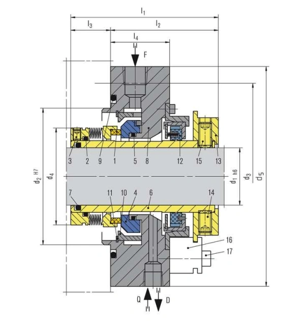
| Inspection Category | Inspection Items | Pusher Seal Requirements | Non-Pusher Bellows Seal Requirements |
|---|---|---|---|
| 1. Operating Conditions | Pump type, fluid, concentration, temperature, pressure, speed, and start-stop frequency. | Verify dynamic O-ring operating conditions. | Verify bellows operating conditions. |
| 2. Seal Design | Seal type, spring design, balance, cartridge or component seal. | Check spring design and dynamic compensation. | Check bellows design and elastic loading. |
| 3. Material Selection | Face, secondary seal, spring, bellows, and sleeve materials. | Focus on dynamic O-ring material. | Focus on bellows alloy and static seal materials. |
| 4. Pressure & Temperature | Maximum pressure, temperature range, maximum speed, and pressure fluctuations. | Check O-ring extrusion risk and face loading. | Check bellows pressure rating and fatigue resistance. |
| 5. Shaft & Dimensions | Shaft diameter, sleeve size, seal chamber, gland, working length, and bolt pattern. | Check sliding surface finish and fit. | Check installation space and axial travel. |
| 6. Support Systems | Flush, Quench, Barrier Fluid, Buffer Fluid, cooling, and drain. | Verify flushing and secondary sealing requirements. | Verify flushing, cooling, and deposit prevention. |
| 7. Quality Control & Testing | Appearance, dimensions, material certificates, pressure, leakage, and assembly checks. | Inspect O-rings, springs, and seal faces. | Inspect bellows, weld quality, and seal faces. |
| 8. Supplier & Delivery | Drawings, BOM, lead time, warranty, spare parts, and repair service. | Confirm O-ring, spring, and face spare parts availability. | Confirm bellows assembly supply and specialist repair capability. |
A spring pushes the moving seal ring axially, and a dynamic O-ring allows the assembly to slide, ensuring that the sealing faces maintain proper contact.
Because the metal bellows provide axial compensation through its own compression and expansion while also serving as a secondary seal, eliminating the need for an O-ring to slide along the sleeve.
Metal bellows seals typically offer an advantage because they reduce reliance on dynamic rubber O-rings. However, the temperature resistance of the bellows alloy, static seals, and face materials must still be verified.
Yes. Pusher seals can be designed as balanced seals, but it is essential to verify the balance coefficient, the risk of O-ring extrusion, and the pressure rating of the specific model.
Metal bellows seals should be considered first when dynamic O-rings are susceptible to high temperatures, chemical erosion, crystalline deposits, or sliding wear.
Common causes include media crystallization, O-ring swelling, long-term hardening due to high temperatures, and scratches or corrosion on the shaft sleeve surface.
Yes. Excessive axial displacement, continuous vibration, pressure fluctuations, and thermal cycling can all increase the risk of bellows fatigue; in severe cases, this may lead to cracking and leakage.
This requires careful evaluation. Although they can reduce dynamic O-ring sticking, solid particles may enter the troughs of the bellows, causing deposits, blockages, or wear.
The Pusher Seal relies on springs and a dynamic O-ring to achieve axial compensation, offering advantages such as a proven design, easy procurement, and relatively simple maintenance. The Non-Pusher Bellows Seal, on the other hand, achieves axial compensation through the elastic deformation of the metal bellows itself, eliminating the need for a dynamic O-ring to slide along the sleeve.
At Sakowitz, we understand that reliable sealing begins with choosing the right design for the actual operating conditions. Whether you ultimately choose a Pusher or a Non-Pusher Mechanical Seal, you should assess the suitability of the materials and design based on the medium, temperature, pressure, and equipment operating conditions.
—— We Will Provide You With Professional OEM Solutions.
Whether you require pump bearings, pump valves, mechanical seals, or other custom-engineered components, we support production based on your drawings as well as rapid prototyping.
Please complete the form on the right and upload your technical drawings or specifications. Our engineering team will review your requirements within 24 hours and provide a detailed quotation, application recommendations, and delivery schedule.
Copyright © 2025 Sakowit, All rights reserved.
WhatsApp us