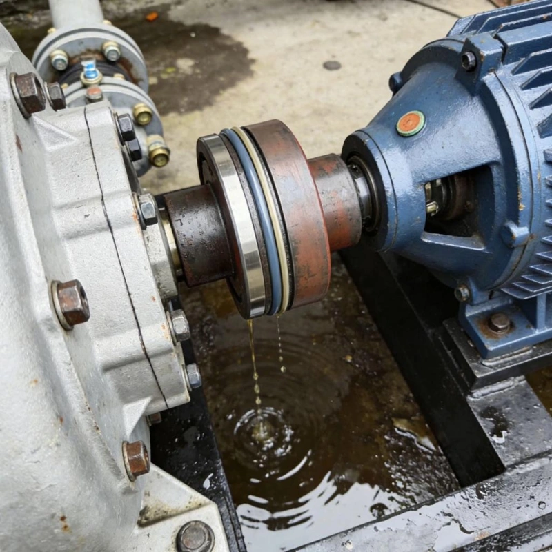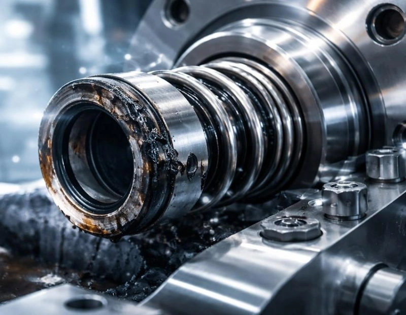

In rotating equipment such as pumps, mixers, and compressors, leak control is a critical factor that determines operational reliability, energy efficiency, and maintenance costs. Mechanical seals are the core components designed specifically for this purpose: they achieve a controlled seal under a thin liquid film using a pair of precisely matched rotating and stationary faces.
This article provides a systematic overview of the basic concepts, main components, operating principles, and common types of mechanical seals, as well as the differences between single-face and double-face seals and between cartridge and component-based designs, to help you establish a comprehensive framework for selection and maintenance.
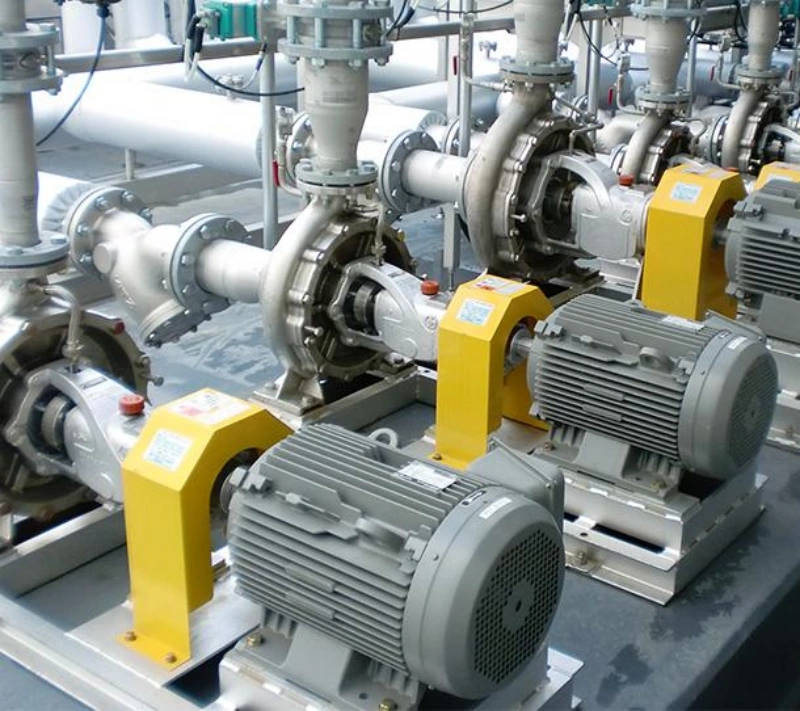
A mechanical seal is a sealing device installed at the shaft end of rotating equipment, primarily used to prevent liquids or gases inside the equipment from leaking outward through the gap between the rotating shaft and the stationary housing.
A mechanical seal primarily consists of the following components:
Rotating Ring: Mounted on the pump shaft or shaft sleeve, it rotates with the shaft.
Stationary Ring: Fixed to the seal gland or seal chamber, it does not rotate with the shaft.
Spring: Provides the necessary axial loading force to maintain contact between the rotating ring and the stationary ring.
Secondary Seals: These include O-rings and other components used to seal the joints between the rotating ring, stationary ring, and other parts.
The most important aspect of understanding mechanical seals is to clearly identify the specific location they seal.
Taking a centrifugal pump as an example, a mechanical seal primarily controls the point where the pump shaft passes through the pump casing, rather than all of the pump’s connection points.
Specifically, mechanical seals primarily control the following two aspects:
When a pump conveys water, lubricating oil, fuel, or chemical liquids, the mechanical seal controls the leakage path through the interaction of two precision-machined faces, reducing media loss and minimizing the risks posed by liquid leakage to equipment, operators, and the surrounding environment.
Under appropriate design and operating conditions, mechanical seals can also reduce the risk of external air, moisture, and contaminants entering the equipment.
For example, when the internal pressure of the pump is lower than the external ambient pressure, external media may enter the pump through poorly sealed areas. A well-designed shaft-end seal helps control this reverse ingress.
Tip: The primary design purpose of a mechanical seal is typically to control the outward leakage of internal media. This does not imply that it can completely prevent external contaminants from entering under all pressure conditions.
In centrifugal pumps, the mechanical seal is installed behind the impeller, where the pump shaft exits the pump casing. This specific installation location is called the seal chamber, also commonly referred to as the stuffing box area.
Mechanical seals are not limited to centrifugal pumps.
They are also widely used in:
Centrifugal Pumps: To prevent leakage of the pumped liquid along the pump shaft.
Chemical Pumps: To control leakage of corrosive or hazardous process media.
Mixers and Agitators: To prevent leakage of liquids or gases from inside the vessel along the rotating shaft.
Compressors: To use specially designed contact or non-contact mechanical seals based on the medium and equipment requirements.
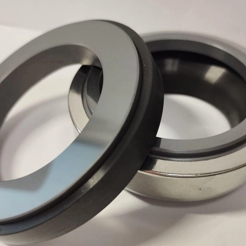
The key to controlling leakage in mechanical seals lies in the precise fit between the rotating ring and the stationary ring. The two sealing faces form a very narrow sealing gap, making it difficult for the liquid inside the pump to flow outward along the rotating shaft.
The rotating ring rotates with the pump shaft, while the stationary ring is fixed within the seal gland or seal chamber. Although their motion patterns differ, their sealing faces must maintain good parallelism, flatness, and surface quality in order to reliably control leakage.
The rotating ring is a sealing ring mounted on the pump shaft or shaft sleeve. Once the pump starts, the rotating ring rotates with the shaft, causing its sealing face to move relative to the face of the stationary ring. Its primary function is to provide a stable, precision-fit rotating sealing surface.
The stationary ring is mounted inside the seal gland or seal chamber and remains stationary during normal operation. The side facing the rotating seal is precision-machined to form another sealing face. The primary function of the stationary seal is to provide a stable, fixed sealing surface that forms a precise fit with the rotating seal.
Tip: The rotating and stationary seals do not simply rely on the two surfaces being pressed tightly together to prevent leakage. What truly affects sealing performance are the microscopic gaps between the two faces, as well as the closing force and fluid-induced opening force acting on the faces.
The rotating and stationary rings control leakage primarily through three interrelated factors: precision face contact, axial closing force, and a stable liquid film.
The sealing faces of the rotating and stationary rings are precision-ground to ensure high flatness and surface quality.
When the mechanical seal is operating normally, the clearance between the two sealing faces is extremely small. This significantly increases the resistance to fluid flow through the clearance, thereby limiting leakage.
The mechanical seal uses springs to provide an axial closing force, ensuring that the rotating and stationary rings maintain proper contact.
At the same time, the fluid pressure within the seal chamber acts on the sealing faces, generating a corresponding axial force.
In a standard liquid mechanical seal, a very thin fluid film exists between the rotating and stationary rings. This film reduces friction between the two faces and helps dissipate some of the heat generated during operation.
As the rotating ring turns, the fluid between the faces is affected by viscous shear and the microscopic geometry of the faces, resulting in a corresponding distribution of fluid film pressure.
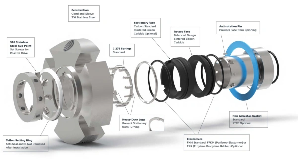
A mechanical seal is not composed of a single sealing ring, but rather a sealing system consisting of multiple components that work together.
The rotating ring is one of the primary sealing components of a mechanical seal. It is mounted on the pump shaft or shaft sleeve and rotates with the shaft. The precision-machined surface facing the stationary ring is called the sealing face, which is the key area for controlling fluid leakage.
Tip: The rotating ring is not necessarily made of a hard material, and its sealing performance cannot be determined solely based on material hardness. Actual selection must also consider the material pairing between the rotating and stationary rings, lubrication conditions, and the risk of thermal deformation.
The stationary ring is installed within the seal gland or fixed seal seat and does not rotate with the pump shaft during normal operation. Together with the sealing face of the rotating ring, it forms the primary sealing barrier.
Auxiliary seals are primarily used to prevent fluid leakage between the seal rings and the shaft sleeve, seal seat, or other mating components. Common types include O-rings, wedge-shaped seals, and PTFE sealing elements.
Common materials for auxiliary seals include:
| Material | Main Features | Selection Notes |
|---|---|---|
| NBR | Commonly used with some mineral oils and general industrial fluids. | Temperature and chemical resistance depend on the fluid and compound. |
| FKM | Good resistance to many oils, fuels, and chemicals. | Not suitable for all hot water, steam, or chemical applications. |
| EPDM | Commonly used in hot water, some steam, and water-based fluids. | Generally unsuitable for mineral oils and many petroleum-based fluids. |
| PTFE | Broad chemical resistance. | Limited elasticity; seal design must be considered. |
| FFKM | Some grades suit aggressive chemicals and high temperatures. | High cost; verify the specific grade and operating limits. |
The primary function of springs or bellows is to provide the necessary axial loading force to ensure that the rotating and stationary rings maintain proper contact during equipment startup, shutdown, and normal operation.
Common elastic loading structures include single springs, multiple springs, and bellows.
Tip: Springs are not the sole source of closing force for mechanical seals. In actual operation, medium pressure and the seal design also affect the forces acting on the sealing faces. It is incorrect to simply assume that a stronger spring results in better sealing performance.
Drive components are used to transmit the rotational motion of the pump shaft to the rotating ring and ensure that the correct motion relationship is maintained between the rotating ring and the shaft.
If the drive components are loose, worn, or installed incorrectly, the rotating ring may not rotate stably with the shaft, potentially leading to abnormal friction, component damage, or seal failure.
The gland plate is a structural component used to secure the mechanical seal assembly and connect it to the pump casing or seal chamber. It is bolted to the pump casing and, in conjunction with gaskets or other static seals, prevents the medium from leaking between the gland plate and the pump casing.
The shaft sleeve is a protective component installed on the outside of the pump shaft. It provides a sealing mounting surface and, when properly designed, reduces wear caused by direct contact between the sealing elements and the pump shaft.
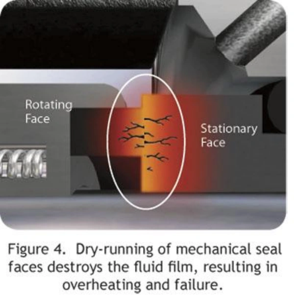
In a mechanical seal, a fluid film exists between the two sealing faces, reducing friction between them and dissipating some of the heat generated during operation.
The fluid film is an extremely thin layer of fluid that exists between the sealing faces of the rotating ring and the stationary ring.
When the pump is operating, the rotating ring rotates with the shaft, while the stationary ring remains fixed. Relative motion occurs between the two sealing faces, and the sealing medium forms a lubricating fluid film under the combined effects of viscous shear, the geometry of the sealing faces, and the pressure distribution.
During mechanical seal operation, relative motion occurs between the rotating and stationary rings. If the two sealing faces were completely deprived of lubrication, microscopic surface irregularities might come into direct contact, generating significant frictional resistance.
The primary function of the fluid film is to reduce this direct contact and minimize friction between the sealing faces.
During the operation of a mechanical seal, frictional heat is generated between the rotating ring and the stationary ring.
If this heat cannot be dissipated in a timely manner, the face temperature may continue to rise, affecting material performance and seal stability. The fluid film plays a crucial role in heat transfer here.
This is manifested in three ways:
The liquid film must maintain an appropriate thickness and stability. If the liquid film is too thin, breaks up in certain areas, or vaporizes, it may affect the lubrication and cooling of the end face.
The following are several common scenarios.
| Fluid Film Issue | Possible Cause | Effect on Mechanical Seal |
|---|---|---|
| Insufficient Fluid Film | Inadequate fluid supply, dry running, or poor lubrication. | Increased friction and face overheating. |
| Local Film Breakdown | Face deformation, pressure fluctuations, or unstable lubrication. | Localized wear and increased leakage. |
| Film Vaporization | Excessive temperature or local pressure below fluid vaporization conditions. | Reduced film load capacity and unstable seal operation. |
| Excessively Thick Film | Excessive face-opening force or abnormal design conditions. | May increase leakage. |
| Particle Contamination | Solids in the process fluid or external contaminants. | Face scratching and wear. |
| Comparison | Mechanical Seal | Gland Packing |
|---|---|---|
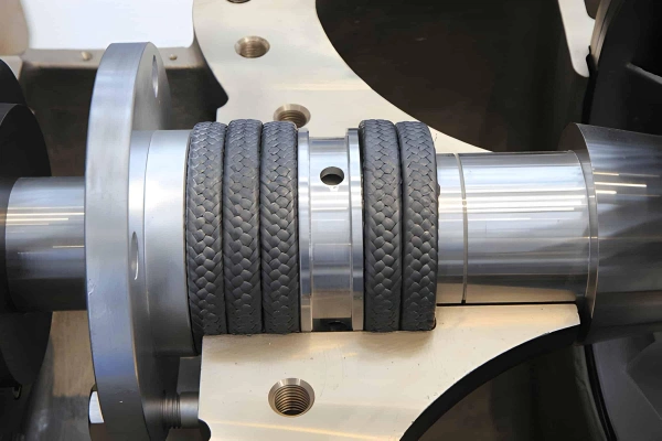
| Working Principle | Controls leakage through rotating and stationary seal faces. | Compresses packing against the shaft sleeve to restrict leakage. |
| Sealing Structure | Rotating ring, stationary ring, springs, and secondary seals. | Packing rings, stuffing box, and gland follower. |
| Leakage Control | Low leakage; suitable for strict leakage control. | Allows controlled leakage. |
| Fluid Loss | Generally lower. | Generally higher. |
| Friction | Mainly between rotating and stationary faces. | Mainly between packing and rotating shaft sleeve. |
| Energy Consumption | Generally lower; depends on face load and lubrication. | Generally higher due to packing compression and friction. |
| Shaft Wear | Minimal direct shaft sleeve wear in normal operation. | Prolonged contact may cause sleeve wear and grooves. |
| Maintenance | Less frequent adjustment; requires condition monitoring. | Requires periodic gland adjustment and packing replacement. |
| Installation | Requires precise installation, clean faces, and proper shaft condition. | Simple structure with easier installation and adjustment. |
| Service Life | Depends on face materials, lubrication, and operating conditions. | Depends on packing material, compression, and lubrication. |
| Initial Cost | Generally higher. | Generally lower. |
| Replacement Cost | Seal assembly replacement can be expensive. | Packing replacement is generally less expensive. |
| Operating Cost | Generally lower fluid loss and friction losses. | May involve higher fluid loss and maintenance costs. |
| Pressure Capability | Balanced designs can handle higher pressures, depending on design. | Limited by packing design, compression, and material capability. |
| Temperature Capability | Depends on face materials, secondary seals, and lubrication fluid. | Depends on packing material and lubrication. |
| Speed Capability | Suitable for higher speeds with proper heat control. | Friction heat and wear increase at higher speeds. |
| Clean Fluids | Generally suitable with good leakage control. | Suitable, but controlled leakage must be managed. |
| Abrasive Fluids | May require wear-resistant faces, flushing, and special designs. | Useful in some slurry and wastewater applications, but packing wear must be monitored. |
| Chemical Compatibility | Check face, secondary seal, and metal materials. | Check packing, shaft sleeve, and auxiliary materials. |
| Environmental Protection | Better suited to applications requiring strict leakage control. | Requires leakage collection and management. |
| Typical Applications | Chemical pumps, oil pumps, pharmaceutical equipment, and high-value fluid transfer. | Wastewater pumps, some slurry pumps, circulating water pumps, and equipment allowing controlled leakage. |
When selecting a mechanical seal, you need to consider not only the sealing materials and operating conditions, but also determine the seal configuration and installation design.
A single-face mechanical seal is a type of mechanical seal configuration that is relatively simple in structure and widely used.
It has only one set of primary sealing faces, consisting of a rotating ring and a stationary ring. The rotating ring rotates with the pump shaft, while the stationary ring is fixed within the seal gland or seal seat; the two control medium leakage through a precision face-to-face fit.
Tip: A single-face mechanical seal is not necessarily unsuitable for high-pressure or high-temperature operating conditions. Its specific capabilities depend on the seal design, materials, auxiliary systems, and actual operating parameters.
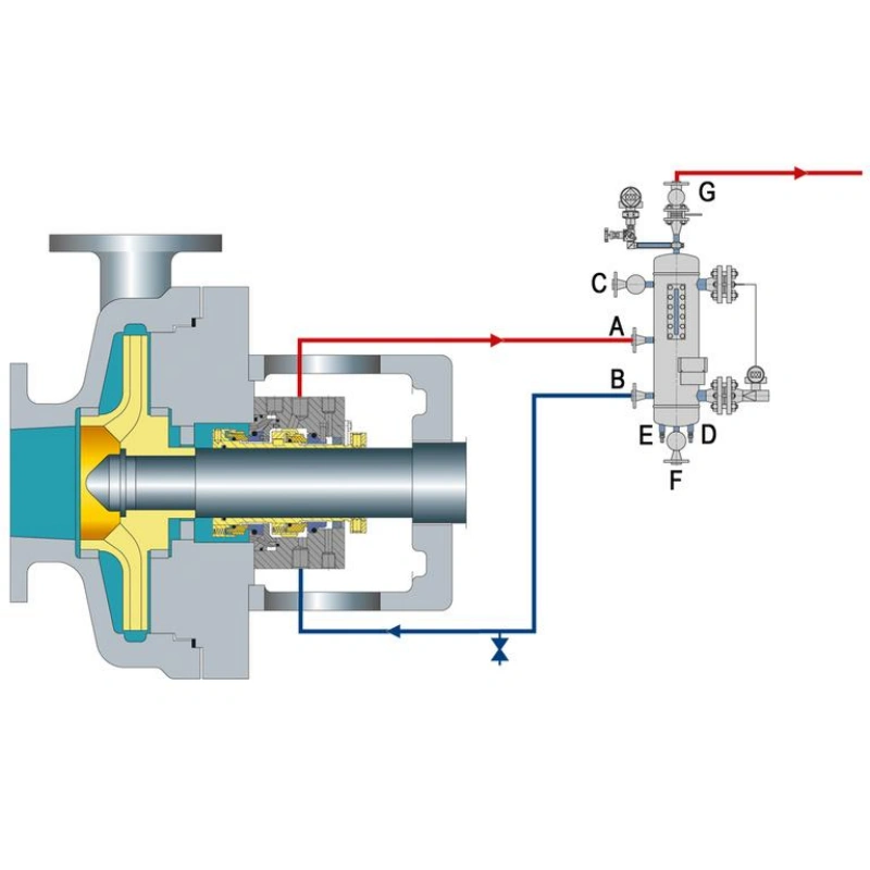
A double-face mechanical seal uses two sets of mechanical seal faces, consisting of an inner seal and an outer seal.
An independent space, known as an isolation chamber, is formed between the two sets of seals. Buffer fluid or isolation fluid can be introduced into this space to help control leakage and improve lubrication and cooling conditions.
Double-face mechanical seals are primarily divided into two configurations:
The unpressurized double-face mechanical seal is also known as a non-pressurized double seal.
Its main characteristic is that the pressure of the buffer fluid between the two sets of seals is lower than the pressure in the pump’s seal chamber.
A pressurized dual-face mechanical seal is also known as a pressurized dual seal.
The main difference between this and the unpressurized configuration is that the pressure of the isolation fluid between the two sets of seals is higher than the pressure in the pump’s seal chamber.
During normal operation, the isolation fluid flows from the intermediate chamber toward the process side and the outer side. This reduces the likelihood of process medium leakage to the outside and provides lubrication and cooling for the sealing faces of both sets of seals.
| Comparison | Single Seal | Dual Seal |
|---|---|---|
| Seal Face Sets | One set. | Two sets. |
| Seal Structure | Relatively simple. | More complex. |
| Seal Chamber | Usually no separate barrier chamber. | Intermediate chamber between the two seal sets. |
| Support Fluid | Usually lubricated by process fluid. | Uses Buffer Fluid or Barrier Fluid, depending on design. |
| Leakage Control | Controls process fluid leakage outward. | Provides an additional sealing barrier and controls leakage direction. |
| Safety Protection | Relies on one seal set and its support measures. | Provides additional leakage containment protection. |
| Cooling & Lubrication | Usually relies on process fluid or external flushing. | Can use buffer or barrier fluid. |
| System Complexity | Low. | High. |
| Initial Cost | Generally lower. | Generally higher. |
| Maintenance | Relatively simple. | Requires monitoring of both seals and support systems. |
| Typical Applications | Industrial water pumps and general fluid transfer. | Hazardous fluids and applications requiring strict leakage control. |
A cartridge-type mechanical seal is a design in which the main sealing components are pre-assembled into a complete unit.
It includes the rotating ring, stationary ring, springs, auxiliary seals, shaft sleeve, seal gland, and related drive components.
These parts are pre-assembled at the manufacturer’s facility, with their installation positions and operating lengths set according to design specifications. During installation, you simply mount the complete seal assembly onto the pump shaft and secure the gland to the equipment.
A component-type mechanical seal refers to a structure in which the main parts of the mechanical seal are supplied separately and must be installed and adjusted one by one on the equipment.
It consists of independent rotating ring assemblies, stationary ring assemblies, springs, auxiliary seals, and other connecting parts.
Unlike the pre-assembled structure, component-type mechanical seals typically do not include a complete, preset shaft sleeve or an integrated positioning structure.
| Comparison | Cartridge Seal | Component Seal |
|---|---|---|
| Supply Format | Pre-assembled as a complete unit. | Individual components supplied separately. |
| Installation | Installed as one complete assembly. | Components installed and adjusted individually. |
| Installation Accuracy | Requires less on-site adjustment. | Requires precise measurements and installation. |
| Spring Setting | Pre-set by the manufacturer. | Usually adjusted on-site according to design requirements. |
| Installation Difficulty | Generally lower. | Generally higher. |
| Installation Error Risk | Relatively low. | More dependent on installer skills. |
| Maintenance | Can be removed or replaced as a complete unit. | Individual components can be removed and replaced. |
| Initial Cost | Generally higher. | Generally lower. |
| Repair Flexibility | Depends on design and spare parts availability. | More flexibility for individual component replacement. |
| Typical Applications | Chemical pumps, continuous-duty equipment, and applications requiring quick maintenance. | General industrial pumps and equipment with established maintenance facilities. |
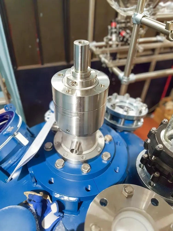
Mechanical seals are widely used in various types of industrial rotating equipment, primarily to prevent liquids or gases from leaking through the gap between the rotating shaft and the stationary housing.
Centrifugal pumps are one of the equipment types in which mechanical seals are most widely used.
Centrifugal pumps generate centrifugal force through the rotation of an impeller, imparting energy to the liquid and conveying it through the pump discharge. In this process, the pump shaft must pass through the pump casing and connect to the internal impeller; therefore, a reliable sealing structure must be installed between the shaft and the pump casing.
Chemical pumps are widely used in petrochemical, fine chemical, pharmaceutical, and other industrial production processes.
The media transported by this type of equipment may be corrosive, toxic, volatile, or flammable. Therefore, in addition to ensuring normal equipment operation, it is essential to strictly control leaks of process media.
Mechanical seals reduce the risk of liquid leakage from the pump shaft, minimizing media loss and the impact on the operating environment.
Mixers and agitators are primarily used to thoroughly blend liquids, powders, or different materials inside vessels.
In this type of equipment, a motor drives the rotation of the agitator shaft, which passes through the shell of the reactor or storage tank; therefore, a sealing device must be installed at the shaft penetration point.
Mechanical seals are installed at the point where the agitator shaft connects to the equipment shell to prevent the leakage of liquids or gases from inside the vessel.
Compressors are used to increase gas pressure and are widely used in natural gas, petrochemical, refrigeration, and industrial gas transmission systems.
Unlike liquid pumps, compressors primarily handle gases; therefore, their sealing designs must take into account the gas’s pressure, temperature, leakage characteristics, and lubrication conditions.
Some centrifugal compressors use dry gas seals.
Steam turbines and gas turbines are also typical examples of high-speed rotating equipment.
They use steam or high-temperature combustion gases to drive the rotor, and are primarily used in power generation, energy, and industrial power systems.
Steam turbines and gas turbines employ sealing configurations such as labyrinth seals, carbon ring seals, or brush seals, depending on the equipment’s location, temperature, pressure, and design requirements.
To determine whether a mechanical seal is suitable for your pump, you cannot rely solely on the seal model, material hardness, or the maximum operating pressure and temperature specified on the product label.
What truly determines whether a seal can operate stably is its ability to adapt to the actual operating conditions of the equipment and maintain reliable sealing performance during startup, normal operation, shutdown, and abnormal conditions.
Operating pressure directly affects the stress conditions on the mechanical seal faces. You must focus on the pressure within the seal chamber; you cannot simply use the pump discharge pressure as a substitute.
The seal chamber is the space where the mechanical seal is installed and operates, located between the pump shaft and the pump casing. The actual pressure within the seal chamber may differ from the pump’s suction or discharge pressure.
Temperature not only determines whether the sealing materials can function properly but also affects the lubrication condition of the sealing faces, thermal deformation, and the performance of auxiliary sealing components.
You must distinguish between the medium temperature and the actual operating temperature of the sealing faces. When the two sealing faces move relative to each other, frictional heat is generated; therefore, the local temperature at the faces may be higher than the medium temperature measured within the seal chamber.
Shaft speed determines the relative motion speed of the sealing faces and is a key factor affecting friction, heat generation, and wear.
The two faces of a mechanical seal are associated with the rotating shaft and the stationary structure, respectively. When the pump is operating, the rotating face moves relative to the stationary face, and a stable lubricating fluid film must be maintained between them.
The properties of the fluid are one of the key factors determining the suitability of a mechanical seal. Even if the pressure, temperature, and rotational speed are all within the seal’s permissible range, the seal may still fail prematurely if the fluid cannot provide an adequate lubricating environment or if it corrodes the seal components.
You should pay close attention to the following aspects.
If your pump handles slurries, wastewater, mineral slurries, or chemical media containing solid particles, you need to pay special attention to the impact of these solid particles on the seal faces.
Abrasive particles are solid particles capable of damaging material surfaces through friction or impact.
When particles enter the space between the seal faces, they can cause scratches, wear, or even damage to the originally smooth sealing surfaces.
You also need to consider whether the pump operates continuously, intermittently, or with frequent starts and stops.
This is because the operating environment of a mechanical seal is not always stable. Phases such as startup, shutdown, standby, and flushing can all alter the pressure, temperature, and lubrication conditions near the seal faces.
Among these, dry running is a situation that requires special attention when designing mechanical seals.
Even if the materials and operating parameters of the mechanical seal itself meet the requirements, significant vibration, eccentricity, or axial movement of the pump shaft can still affect the normal operation of the seal.
A mechanical seal requires a stable relative position between its two sealing faces. If the pump shaft operates unsteadily, uneven contact may occur between the sealing faces, leading to localized wear, vibration, and leakage.
It typically lasts for several years, depending on the medium, temperature, pressure, lubrication conditions, and installation quality.
Type 2 generally refers to a non-thrust-ring elastomer bellows mechanical seal, commonly used in industrial pumps.
No. Some seals can be lubricated and cooled by the pumped medium; external flushing or cooling is only required under special operating conditions.
Yes. In most cases, the auxiliary seals can be replaced and the sealing faces can be repaired; however, replacement is necessary in cases of severe damage.
Not necessarily. While some seals support bidirectional rotation, directional designs must operate in the specified direction.
Not necessarily. It is necessary to verify that the installation dimensions, design, materials, and operating parameters are compatible.
These primarily include shaft diameter, working length, seal chamber dimensions, gland dimensions, and face dimensions.
Not necessarily. This should be determined based on the amount of leakage, its duration, and the manufacturer’s specifications; persistent or significant leakage requires prompt inspection.
Understanding the structure and operating principles of mechanical seals is the foundation for proper selection and maintenance. Whether single-face or double-face seals, or cartridge-type or component-type designs, each configuration has distinct application characteristics. You need to select the appropriate configuration based on the equipment type, the properties of the medium, and leakage control requirements.
Sakowitz is committed to providing mechanical seal solutions for industrial pumps and rotating equipment. Selecting the right mechanical seal not only reduces the risk of media leakage and equipment maintenance but also enhances the reliability of equipment operation.
—— We Will Provide You With Professional OEM Solutions.
Whether you require pump bearings, pump valves, mechanical seals, or other custom-engineered components, we support production based on your drawings as well as rapid prototyping.
Please complete the form on the right and upload your technical drawings or specifications. Our engineering team will review your requirements within 24 hours and provide a detailed quotation, application recommendations, and delivery schedule.
Copyright © 2025 Sakowit, All rights reserved.
WhatsApp us