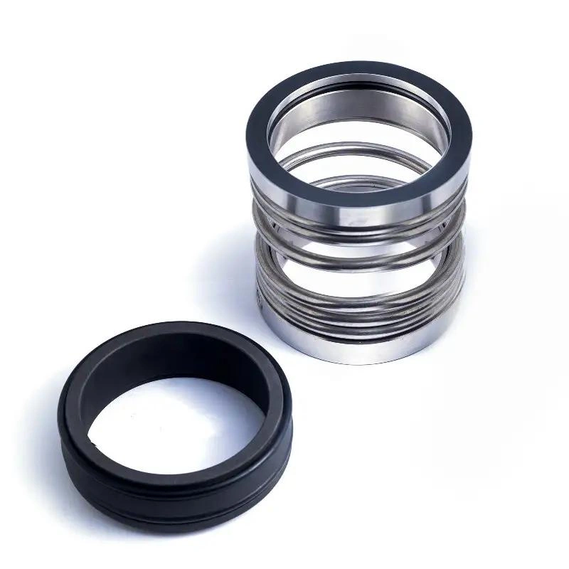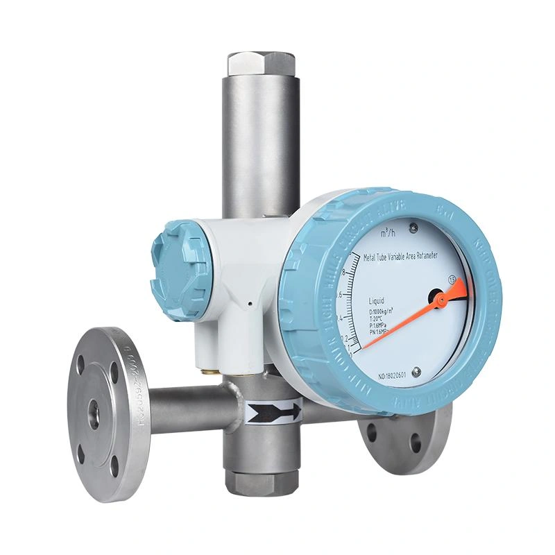

Should mechanical seals be flushed or quenched? Flushing is performed on the medium side of the seal, while quenching is performed on the atmospheric side—that is, the side facing away from the medium.
Understanding this difference in location is the first step toward choosing the right solution.
This article will begin by examining the medium’s flow path and the points of action. It will compare the pressure, flow rate, and medium requirements for flushing and quenching, and explain their different roles in temperature control, lubrication, and deposit prevention, among other aspects. This will help you determine when to use flushing, when to use quenching, and when to combine the two.
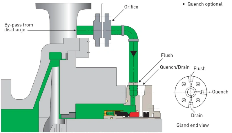
A mechanical seal prevents the fluid inside the pump from leaking outward along the rotating shaft through the sealing faces between the rotating ring and the stationary ring. The core difference between “Flush” and “Quench” lies in their points of application and the specific problems they address.
“Flush” refers to the process of introducing an appropriate fluid into the seal chamber—through internal circulation, recirculation of the pumped medium, or an external fluid supply—to improve the operating conditions near the sealing faces.
Tip: When a pump handles high-temperature liquids, the sealing faces may overheat due to friction and the temperature of the medium. In such cases, a properly designed flushing system can dissipate some of the heat, helping to maintain a stable liquid film and reduce the risk of seal failure caused by overheating or insufficient lubrication.
“Quench” refers to the introduction of an appropriate auxiliary medium—such as water, steam, or nitrogen—into the atmospheric side of a mechanical seal to improve the operating environment on the outside of the seal.
Tip: In certain high-temperature hydrocarbon service conditions, steam quenching can be used to reduce coking on the atmospheric side; for some low-temperature applications, nitrogen may be used to reduce the risk of icing.
| Comparison | Flush | Quench |
|---|---|---|
| Location | Process side | Atmospheric side |
| Main Purpose | Control temperature, lubrication, and seal chamber conditions. | Reduce deposits, coking, oxidation, or icing. |
| Common Fluids | Process fluid or compatible external flush fluid. | Water, steam, nitrogen, etc. |
| Effect on Seal Film | Directly improves lubrication near the seal faces. | Does not maintain the process-side lubricating film. |
| Typical API Plan | Plan 11, Plan 32 | Plan 62 |
| Interchangeable? | No | No |
When selecting a seal, you should first determine on which side the problem lies.
If the seal is primarily exposed to high temperatures, insufficient face lubrication, or unstable fluid conditions within the seal chamber, you should first assess whether a Flush system can address these issues. If the seal is primarily subject to crystallization, coking, or freezing of the leaking medium on the atmospheric side, you should consider a Quench system.
Many people mistakenly believe that Quench can replace Flush in providing lubrication to the seal faces. They also think that simply installing Flush will prevent deposits from forming on the atmospheric side. In reality, the two systems have different scopes of application. The choice must be based on specific failure risks.
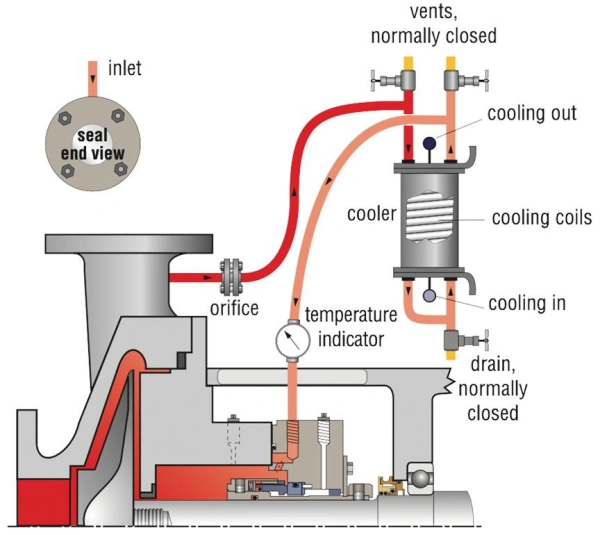
The operating principle of mechanical seal flushing involves using a pressure differential or other circulating force. It directs the flushing fluid into the seal chamber. The fluid flows near the sealing faces. This process removes heat. It improves lubrication conditions. It also reduces the accumulation of contaminants.
Tip: The flushing fluid is not injected directly between the two sealing faces; instead, it first enters the seal chamber and then improves the operating environment by flowing near the sealing faces.
You can think of the flushing process as three consecutive steps: obtaining the flush fluid, delivering it to the seal chamber, and allowing it to flow near the sealing faces.
Step 1: The flush fluid must come from a suitable source.
Common methods include diverting a portion of the process fluid from the high-pressure area of the pump or using a separate, external source of clean fluid.
Step 2: The flush fluid enters the flush port on the seal chamber through piping.
If a pressure-driven circulation system is used, sufficient pressure differential is required to maintain flow.
Step 3: The fluid flows within the seal chamber, passes near the sealing faces, and continues to circulate or returns to the process system via the path specified by the design.
| Flush Method | How It Works | Best For | Key Notes |
|---|---|---|---|
| Internal Circulation | Uses internal pump flow to circulate process fluid near the seal. | Clean fluids and low seal heat loads. | Verify sufficient circulation in the seal chamber. |
| Process Fluid Recirculation | Routes process fluid from a pressure zone back to the seal chamber, e.g. API Plan 11. | Clean fluids with low fouling or crystallization risk. | Check pressure differential, flow rate, and abrasive particles. |
| External Flush | Supplies clean, compatible fluid from an external source, e.g. API Plan 32. | Dirty, poorly lubricating, or unsuitable process fluids. | Check compatibility, dilution, contamination, and supply pressure. |
When selecting a model, simply confirming that the flush lines are connected does not guarantee that the seal is being effectively flushed. You must also verify three key conditions.
For flush schemes that rely on pressure differential, you must verify sufficient pressure. This pressure must drive fluid circulation. Check this during normal operation. Check it during startup. Also check it during low-load conditions. If the pressure differential is insufficient, the actual flush flow rate may be inadequate. This can happen even if the lines are installed.
The location of the flushing port, the structure of the seal chamber, and the clearance of the throttling sleeve all affect flushing effectiveness.
The flushing fluid must meet requirements regarding seal material compatibility, temperature, cleanliness, and process compatibility. Incorrect use of flushing fluids containing particles or prone to crystallization may clog flow channels, damage the sealing faces, or even shorten the seal’s service life.
Tip: If you notice an abnormal rise in seal temperature, do not immediately assume that the flushing flow rate needs to be increased. Instead, first check whether the flushing lines are blocked, whether the supply pressure differential is sufficient, and whether the fluid is circulating effectively within the seal chamber.
Mechanical seal quenching refers to the introduction of an appropriate auxiliary medium into the atmospheric side of the seal to prevent issues such as crystallization, coking, oxidation, or freezing of the leaking medium in the air.
Depending on the properties of the process medium, the quench primarily functions in the following three ways.
Under low-temperature or cryogenic conditions, the cold surface on the atmospheric side of the seal may cause moisture in the air to condense and freeze, forming a layer of ice.
In such cases, consider using dry nitrogen for quenching to reduce the risk of icing by lowering the moisture content in the local environment. However, nitrogen does not necessarily raise the seal temperature; its primary function is to isolate moist air.
When selecting a quench medium, you should first assess what issues might arise on the atmospheric side of the seal and then determine the appropriate auxiliary medium, rather than simply assuming that all mechanical seals should use water for quenching.
| Quench Medium | Main Purpose | Typical Applications | Key Notes |
|---|---|---|---|
| Clean Water | Removes deposits and provides cooling. | Crystallizing or salt-forming fluids compatible with water. | Check compatibility, water quality, and drainage. |
| Low-Pressure Steam | Reduces air contact, coking, and deposits. | High-temperature hydrocarbon services. | Check steam pressure, temperature, and condensate drainage. |
| Nitrogen | Creates a dry atmosphere and limits air or moisture exposure. | Oxidation-sensitive or low-temperature services. | Check pressure, flow rate, and ventilation safety. |
Tip: The quenching medium should not be substituted arbitrarily. For example, for media that react adversely when exposed to water, using water for quenching may create new safety risks; for operating conditions that require strict temperature control, using steam may also introduce additional heat loads.
Although mechanical seal flushing and quenching both require control of the pressure, flow rate, and quality of the auxiliary medium, there are significant differences in their design requirements.
You cannot directly use the same pressure, flow rate, or medium standards to design both systems. The correct approach is to first clarify the function of the auxiliary medium, and then determine the operating parameters based on the seal configuration, process conditions, and manufacturer’s requirements.
For flushing, the key factor regarding pressure is whether sufficient flow driving force can be established. For example, API Plan 11 utilizes the pressure differential between the pump discharge and the seal chamber to direct the process fluid through a restrictor orifice into the seal chamber. If the pressure differential is insufficient, the flush flow rate may fail to meet the seal’s cooling requirements.
However, pressure requirements vary among different flush configurations. For instance, API Plan 32 uses an external cleaning flush fluid, and the supply pressure must exceed the seal chamber pressure to ensure a continuous flow of flush fluid into the seal chamber.
Flow refers to the volume of liquid or gas passing through a pipeline per unit of time.
For Flush, the flow rate must be sufficient to dissipate the heat generated by the seal and maintain proper lubrication conditions at the sealing faces.
If the flow rate is insufficient, the temperature inside the seal chamber may rise; however, an excessively high flow rate may also increase energy consumption, cause unnecessary circulation of the process medium, or increase product dilution during external flushing.
Tip: There are no universal flow rates for Flush or Quench that apply to all mechanical seals. You should determine the appropriate flow rate based on the seal size, operating temperature, properties of the medium, and the thermal load and flow rate requirements provided by the manufacturer—rather than simply assuming that a higher flow rate provides better protection.
The properties of the auxiliary medium are equally important.
The fluid used must have appropriate lubricity, cleanliness, and temperature characteristics. If a process fluid containing a large amount of abrasive particles is used directly, the particles may enter the area near the seal faces and accelerate wear.
If an external flushing fluid is used, it is necessary to confirm its compatibility with the process medium and seal materials, and to assess the risk of product contamination or dilution.
The medium must be selected based on the protection requirements of the atmospheric side. Common options include clean water, low-pressure steam, and nitrogen.
For example, clean water can be used in some applications where water-soluble crystals are likely to form; steam can be used to reduce coking in certain high-temperature hydrocarbon media; and dry nitrogen can be used to reduce the risk of icing in low-temperature applications.
| Comparison | Flush | Quench |
|---|---|---|
| Location | Process side of the seal. | Atmospheric side of the seal. |
| Pressure | Requires sufficient differential or external supply pressure. | Uses low-pressure auxiliary fluid. |
| Flow | Supports cooling, lubrication, and flushing. | Protects the atmospheric side and removes deposits. |
| Common Media | Process fluid or compatible clean external fluid. | Clean water, low-pressure steam, or nitrogen. |
| Media Quality | Cleanliness, lubricity, temperature, and compatibility. | Compatibility, dryness, or water quality. |
| Typical API Plan | Plan 11, Plan 32 | Plan 62 |
| Main Risks | Low pressure, poor flow, particle wear, contamination. | Incorrect pressure, blocked drain, incompatible medium. |
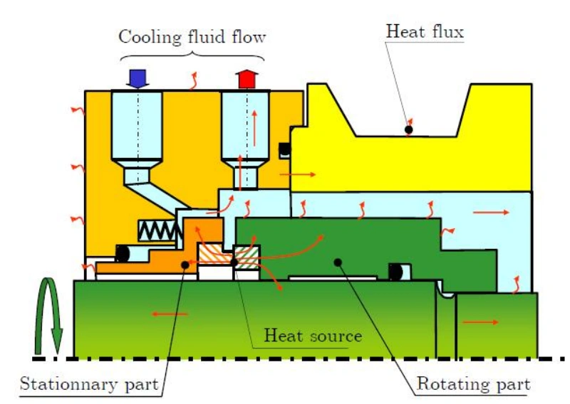
The stable operation of mechanical seals depends primarily on temperature control, face lubrication, and deposit prevention.
During mechanical seal operation, frictional heat is generated between the rotating ring and the stationary ring, and the pumped medium may also transfer heat to the seal chamber.
Flushing can remove heat through liquid circulation and, if necessary, can be combined with a cooler to lower the seal chamber temperature.
Quench may also provide some cooling effect, but it primarily acts on the atmospheric side of the seal and cannot replace the temperature control required on the process side.
Tip: Lower is not necessarily better when it comes to seal temperature. For media that are prone to solidification, crystallization, or a significant increase in viscosity with temperature, excessive cooling may actually cause blockages and deposits. Therefore, the appropriate operating temperature should be determined based on the properties of the medium and the manufacturer’s specifications.
An extremely thin liquid film may exist between the two faces of a mechanical seal to reduce direct contact, friction, and wear. For common liquid-lubricated mechanical seals, the stability of this liquid film is a key factor affecting seal life.
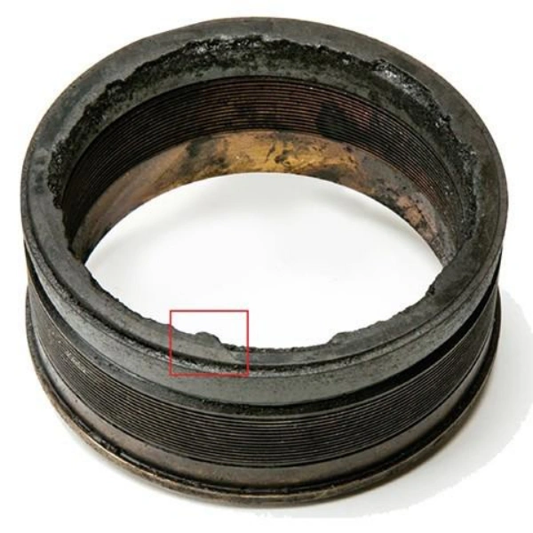
Deposits are an often-overlooked issue in mechanical seal operation. Certain media may produce crystals, coke, polymers, or solid particles when exposed to changes in temperature, pressure, or chemical environment. Once these substances accumulate near the seal, they can interfere with the movement of the seal rings, block the flow passages, or accelerate wear.
| Evaluation | Flush | Quench |
|---|---|---|
| Temperature Control | Removes process-side heat through fluid circulation. | Cools the atmospheric side, not the main process side. |
| Seal Face Lubrication | Supports formation and stability of the process-side fluid film. | Does not replace process-side lubrication. |
| Deposit Prevention | Reduces buildup inside the seal chamber. | Reduces atmospheric-side coking, crystallization, oxidation, or icing. |
| Typical Applications | High temperature, poor lubrication, or dirty seal chamber conditions. | Leakage that may form deposits on the atmospheric side. |
| Main Limitations | Depends on fluid cleanliness, pressure, temperature, and compatibility. | Cannot solve process-side dry running, vaporization, or poor lubrication. |
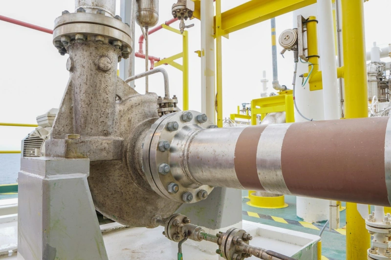
Whether to use flushing, quenching, or both for a mechanical seal depends on the properties of the process medium, the seal’s operating conditions, and the potential risk of failure.
Flushing should be considered when the fluid in the seal chamber cannot provide stable cooling and lubrication.
When a pump handles high-temperature fluids, the frictional heat generated at the seal faces may cause local temperatures to continue rising. If the fluid approaches its vaporization point, this can destabilize the lubricating film on the faces. In such cases, a properly designed flushing circuit can help dissipate heat and improve the seal’s operating environment.
Tip: Not all media are suitable for direct flushing with the fluid itself. If the medium contains a large amount of particles, is prone to polymerization, or forms deposits, direct circulation may fail to resolve the issue and may even exacerbate wear.
Quench should be considered when there is a risk of crystallization, coking, oxidation, or freezing on the atmospheric side of the seal.
Certain high-temperature hydrocarbon media may oxidize or coke upon contact with air after trace leakage from the seal faces. In such cases, low-pressure steam quenching can be considered to reduce deposit formation.
For media prone to forming water-soluble crystals, clean water quenching can be considered to help remove deposits.
Tip: Quench cannot replace the primary seal, nor can it serve as the sole safety control measure for leaks of toxic, flammable, or other hazardous media. For these operating conditions, appropriate sealing and containment systems must also be evaluated based on leak control and safety requirements.
If a mechanical seal faces different issues on both the process side and the atmospheric side simultaneously, it may be necessary for Flush and Quench to work in conjunction.
Certain high-temperature hydrocarbon pumps may face two risks simultaneously: high temperatures in the seal chamber, requiring a flush cycle to control heat; and trace leaks of the medium that are prone to coking upon contact with air, requiring steam quenching to protect the atmospheric side.
| Operating Condition | Preferred Option | Main Reason |
|---|---|---|
| High seal chamber temperature or unstable lubrication | Flush | Improves cooling and fluid film conditions. |
| Process fluid contains abrasive particles | Clean Flush | Reduces particle entry into the seal faces. |
| Atmospheric-side leakage crystallizes easily | Quench | Reduces crystallization and deposits. |
| Hot leakage tends to coke | Quench | Reduces atmospheric-side coking. |
| Atmospheric side may ice in low temperatures | Quench | Limits moisture contact and icing. |
| Process side needs cooling and atmospheric side may coke | Flush + Quench | Controls risks on both sides. |
| Clean fluid, suitable temperature, no major side risks | External supply may not be needed | Avoids unnecessary auxiliary systems. |
Tip: The above provides preliminary guidance for selection and does not represent final design requirements. Some mechanical seals may operate using internal circulation even without external flushing lines; the “Flush” designation in the table does not necessarily mean that an external flushing fluid must be used.
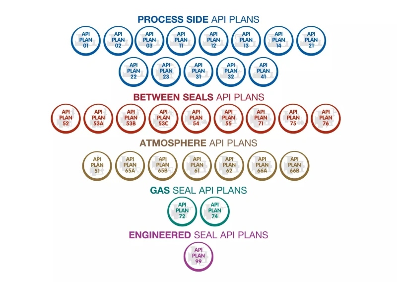
In mechanical seal systems, API Seal Plans are a series of standardized configurations defined by the API 682 standard, used to guide the circulation, cooling, flushing, isolation, and leakage management of seal auxiliary media.
The differences between various API plans lie not only in piping connections but also in the source of the medium, flow paths, cooling capacity, and applicable operating conditions. Therefore, you cannot simply rely on the API Plan number to determine which plan is better; instead, you should select based on the seal configuration, medium properties, and actual operational risks.
Plan 11 is a common flushing scheme. It diverts a portion of the process medium from the pump outlet or another suitable high-pressure area; after passing through a orifice plate, the liquid is delivered to the seal chamber to cool the seal and improve face lubrication conditions.
This scheme features a relatively simple piping configuration and does not require the introduction of additional fluids, making it suitable for clean, non-polymerizing process media at appropriate temperatures.
Plan 21 adds a cooler to a circulation path similar to that of Plan 11. The process medium is diverted from the pump outlet, throttled, and cooled before entering the seal chamber, thereby reducing the flush fluid temperature.
If the temperature of your process medium is high and a standard recirculating flush cannot meet the seal cooling requirements, you may want to evaluate Plan 21.
Plan 23 uses a recirculation system to route the fluid from the sealing chamber through an external cooler before returning it to the chamber.
This approach is commonly used for high-temperature cleaning media, such as certain hot water, boiler feedwater, and high-temperature hydrocarbon applications. However, you must inspect the recirculation system, cooler, venting, and piping layout to prevent poor circulation from compromising cooling performance.
Plan 32 does not rely on the circulation of the process medium itself but instead continuously supplies a compatible, clean flushing fluid to the seal chamber from an independent fluid source.
This approach should be considered when the process medium contains particulates, lacks sufficient lubricity, or is unsuitable for use as a flushing fluid.
Plan 62 is a typical quenching plan that uses external piping to introduce clean water, low-pressure steam, or nitrogen into the atmospheric side of a mechanical seal, thereby reducing problems such as crystallization, coking, or freezing of the leaking medium.
For high-temperature hydrocarbon media prone to coking in air, you may consider steam quenching; for media prone to forming water-soluble crystals, you may evaluate clean water quenching; and for low-temperature conditions where freezing is likely, you may consider dry nitrogen.
Tip: Plan 62 uses a controlled, low-pressure auxiliary medium, and the discharge path must remain unobstructed. It cannot replace process-side flushing, nor should it be used as a leak control measure following primary seal failure.
Plan 61 provides reserved connections on the seal’s atmospheric side, but under normal configuration, no quenching medium is continuously supplied to the seal. You should view this as a provision for the future installation of auxiliary piping, rather than as an operational quenching system.
This approach is suitable for equipment that does not currently require continuous quenching but may need to add quenching or leak collection capabilities in the future.
| Common Mistake | Possible Problem | Correct Approach |
|---|---|---|
| Assuming more flow is always better | Too little causes poor cooling; too much wastes fluid and increases circulation load. | Set flow based on heat load, fluid properties, and manufacturer requirements. |
| Ignoring pressure differential | Low flow, reverse flow, or unstable circulation. | Check supply pressure, seal chamber pressure, and line resistance. |
| Wrong auxiliary fluid | Seal wear, contamination, corrosion, or chemical reaction. | Verify cleanliness, lubricity, and chemical compatibility. |
| Poor piping or blocked drain | Low circulation, trapped gas, liquid buildup, or abnormal pressure. | Check piping, restrictions, vents, and drains. |
| Using Quench to hide seal failure | Leakage continues and seal damage worsens. | Inspect seal faces, installation, and operating conditions. |
| Ignoring routine maintenance | Blocked lines and reduced cooling or flushing performance. | Monitor pressure, flow, temperature, leakage, and drainage. |
Tip: The design requirements for “Flush” and “Quench” differ. When an anomaly occurs, you should first determine whether the problem is on the process medium side or the atmospheric side, and then take targeted measures to avoid blindly increasing pressure or flow rate.
When selecting a mechanical seal support system, you need to comprehensively consider the properties of the process medium, operating temperature, pressure, seal configuration, and leakage control requirements.
When selecting a mechanical seal support system, don’t just start by consulting the API 682 tables; first, clearly break down the issues based on the operating conditions. By following the 5 steps below, you should be able to match the appropriate solutions—such as flushing, quenching, isolation fluid/buffer fluid, and dry gas sealing—to your specific application.
Assess whether the medium is hazardous and whether leakage is permissible.
Focus on the following: temperature, pressure, viscosity, cleanliness, presence of solid particles, tendency to crystallize, coke, or polymerize, tendency to vaporize, corrosiveness, and toxicity.
The objectives of flushing the process side are: to cool the system, increase vaporization margin, maintain face lubrication, and remove contaminants.
Rapid cooling is not intended to cool the process side; it is primarily used to address issues on the atmospheric side: crystallization, coking, oxidation, freezing, and polymer buildup.
Selecting the right solution is only the first step; whether the system can operate reliably on-site depends on the details:
Theoretically, yes, but this is rarely done in practice. Flushing occurs on the process medium side of the sealed chamber, while quenching occurs on the atmospheric side; the two have different functions, pressure requirements, and flow direction requirements. Unless it is an isolation fluid/buffer fluid system (such as Plan 52/53) circulating within the chamber, sharing the same fluid is not recommended.
Under normal circumstances, there is no direct contact. The quench fluid acts on the atmospheric side and is separated by the sealing faces; the two may only come into contact at the point of leakage if there is a trace leak from the faces.
The liquid film on the sealing faces becomes unstable; frictional heat cannot be dissipated, causing the temperature in the seal chamber to rise. This makes the medium prone to vaporization, coking, or crystallization, leading to dry friction, scratches on the sealing faces, or even burnout.
Yes. Excessive pressure can cause the rotating ring to become misaligned, disrupt the face-to-face contact, accelerate wear, and even damage auxiliary sealing components such as O-rings. Generally, the external flush fluid pressure should be 0.05–0.2 MPa higher than the pressure in the seal chamber.
Yes. Steam is one of the commonly used quench media in Plan 62, particularly suitable for high-temperature oil pumps and applications prone to crystallization or coking. It helps maintain temperature, prevent condensation, and flush away deposits. However, care must be taken to control the pressure (typically ≤0.3 MPa) to prevent scalding or the accumulation of condensate.
Common methods include installing a rotameter, a flow switch, or a needle valve with a sight glass, along with a pressure gauge to monitor the pressure differential. The key is to ensure the flow is stable and to check the sight glass for bubbles or impurities; set a low-flow alarm if necessary.
Not necessarily. If the medium temperature is low and the medium is clean, the double mechanical seal can dissipate heat through the circulation of the isolation fluid or buffer fluid alone, so the first seal does not require a separate flushing system. However, flushing is still required under high-temperature, contaminated, or vapor-prone conditions.
Conduct daily patrols to check for leaks, pressure, and flow; inspect filters and orifice plates monthly for clogging; test the physical and chemical properties of the isolation fluid every 3 months; and perform a comprehensive overhaul generally no later than every 3 years or 24,000 hours. Pay special attention to preventing blockages and scaling in quench lines, and protect them from freezing during winter.
Understanding the difference between mechanical seal flushing and quenching is essential for selecting the appropriate seal support system and improving equipment operational reliability. Flushing primarily acts on the process medium side, reducing the risk of seal face overheating and wear by improving liquid circulation, temperature, and lubrication conditions. Quenching, on the other hand, primarily acts on the atmospheric side to mitigate issues such as crystallization, coking, oxidation, or freezing caused by leaked media.
In practical applications, you need to comprehensively consider the properties of the process medium, operating pressure, temperature, seal design, and leakage control requirements.
Sakowitz is committed to helping customers select the appropriate mechanical seals and auxiliary system configurations based on actual operating conditions. We welcome you to contact us!
—— We Will Provide You With Professional OEM Solutions.
Whether you require pump bearings, pump valves, mechanical seals, or other custom-engineered components, we support production based on your drawings as well as rapid prototyping.
Please complete the form on the right and upload your technical drawings or specifications. Our engineering team will review your requirements within 24 hours and provide a detailed quotation, application recommendations, and delivery schedule.
Copyright © 2025 Sakowit, All rights reserved.
WhatsApp us