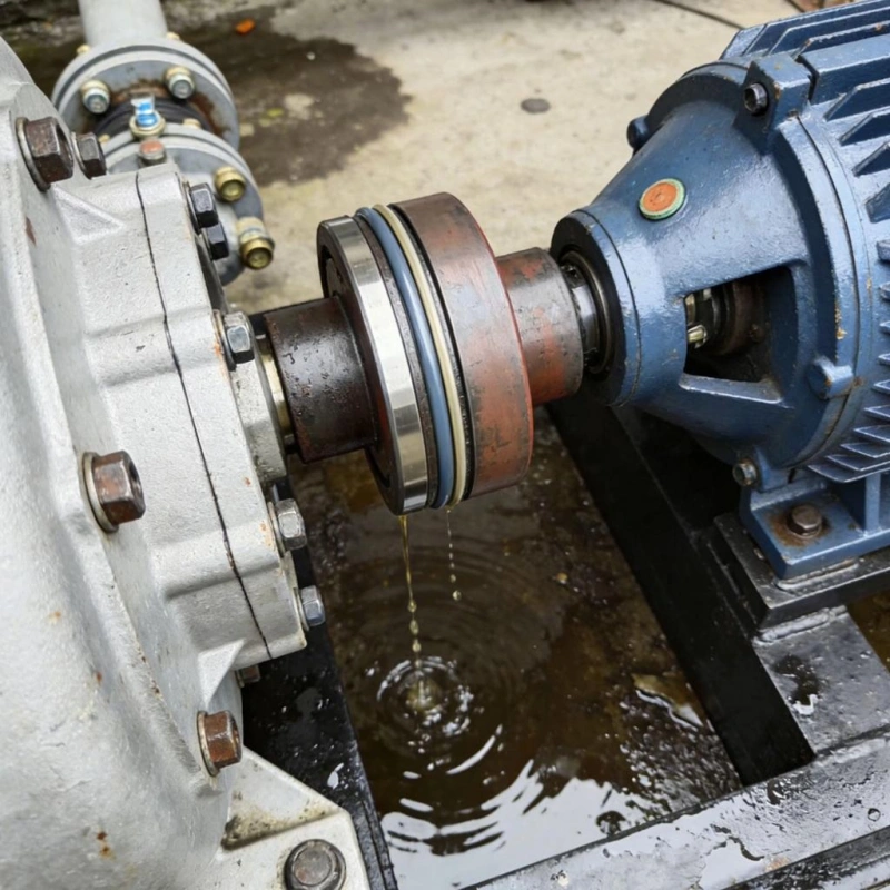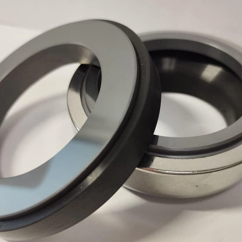

Double-face mechanical seals consist of two sets of sealing faces. The buffer fluid or barrier fluid between the two sets of seals improves sealing performance and reduces the risk of process medium leakage. Common configurations include back-to-back, face-to-face, and in-line types.
This article begins by discussing the classification methods for double-face mechanical seals and compares the characteristics of different configurations, pressure systems, and lubrication methods to help you select the appropriate double-face mechanical seal based on your specific operating conditions.

A double-ended mechanical seal consists of two sets of mechanical seals, one set in contact with the process medium and the other set in contact with the outside of the equipment. An independent space is provided between the two sets of seals, into which liquid or gas can be introduced for lubrication, cooling, or leakage control.
Based on the installation orientation and internal component positioning of the two sets of mechanical seals, common configurations can be divided into three types:
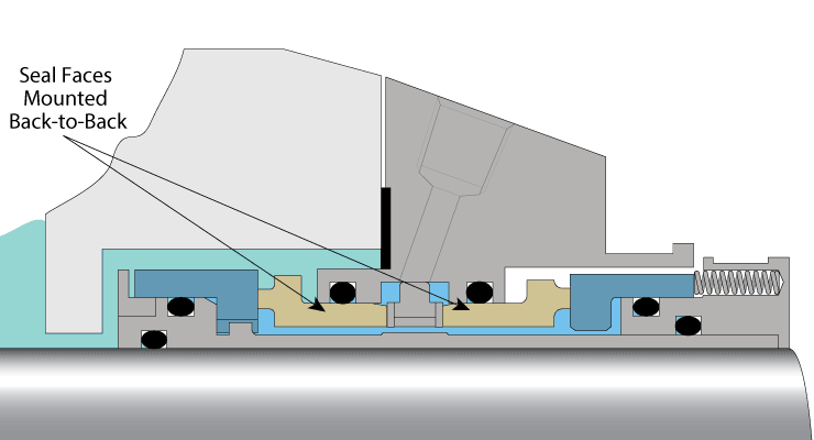
Back-to-Back: The two sets of seals are arranged back-to-back. This configuration is used in double-face seal systems that require pressurized isolation of the medium; however, its suitability must also take into account face cooling, pressure reversal, and medium characteristics.
Face-to-Face: The two seal sets are arranged facing each other. This configuration creates a space for the flow of the medium to be isolated, but its actual cooling effectiveness depends on the internal flow paths and seal design.
Face-to-Back: Also commonly referred to as a series configuration, the two seal sets are arranged axially. This type of configuration can be used in both non-pressurized systems and, in certain designs, pressurized systems.
Tip: These terms describe the specific internal configuration of the seal and cannot be determined solely based on the general orientation of the two sets of sealing faces. When identifying the seal, refer to the cross-sectional diagram provided by the manufacturer to confirm the positions of the rotating ring, stationary ring, and elastic compensation element.
From a practical selection perspective, the medium pressure between the two seal sets is a key factor in determining the type of double-face mechanical seal.
According to API 682, double-face mechanical seals primarily involve the following two arrangements.
| Comparison | Non-Pressurized Dual Seal (Arrangement 2) | Pressurized Dual Seal (Arrangement 3) |
|---|---|---|
| Intermediate Fluid | Buffer Fluid | Barrier Fluid |
| Pressure Relationship | Intermediate pressure is lower than seal chamber pressure. | Intermediate pressure is higher than seal chamber pressure. |
| Main Function | Collects, controls, and monitors process fluid leakage. | Prevents process fluid from leaking outward. |
| Key Characteristic | Process fluid may enter the buffer space through the inner seal. | Barrier fluid may enter the process side under normal pressure differential. |

Double-face mechanical seals can also be classified based on the lubricating medium between the sealing faces and their contact conditions.
Wet-lubricated seals: Rely on a liquid to form a lubricating film between the faces, reducing friction and dissipating heat. The supply, circulation, and cooling conditions of the liquid must be verified.
Gas-lubricated seals: Rely on a gas to form a gas film between the faces. Some designs are non-contact, maintaining a minimal gap during operation to reduce friction. However, requirements for gas purity, pressure, rotational speed, and process compatibility must be met.
Dry-run design: Can operate without liquid lubrication under specified conditions. However, dry running does not mean that lubrication is completely unnecessary, nor does it imply that standard liquid-lubricated seals can operate without liquid for extended periods. Some outer safety seals in non-pressurized double seals are capable of dry running, but this is not the same concept as gas-lubricated non-contact seals.
Step 1: Confirm whether the equipment has two sets of independent mechanical seal faces and whether there is a separate medium space between the two sets of seals.
Step 2: Determine the relationship between the working pressure of the intermediate medium and the pressure in the seal chamber to determine whether it is a pressurized or non-pressurized double seal.
Step 3: Examine the structural cross-sectional diagram to identify the arrangement of the seal faces and confirm whether they are lubricated by liquid or gas, and whether they operate in contact or non-contact mode.

Back-to-back, face-to-face, and in-line are the three common configurations for double-ended mechanical seals. Their main differences lie in the mounting orientation of the two sets of sealing faces, the positioning of internal components, and their ability to adapt to pressure fluctuations, cooling requirements, and media contamination.
Tip: When you need to seal toxic, flammable, or other media that must not leak to the outside, and the process allows for a small amount of barrier fluid to enter, you may consider a back-to-back configuration. It is suitable for many conventional pressurized double-seal applications.
Tip: When requiring that the outer seal be capable of independently withstanding a specified pressure after the inner seal fails, you must verify that the structure possesses this capability; do not rely solely on the double-face design.
| Comparison | Back-to-Back | Face-to-Face | Tandem / Face-to-Back |
|---|---|---|---|
| Arrangement | Two seals face outward. | Two seals face inward. | Two seals arranged in series along the shaft. |
| Typical Pressure Setup | Pressurized barrier system. | Pressurized barrier system. | Pressurized or unpressurized, depending on design. |
| Main Advantage | Suitable for pressurized dual seals and barrier fluid cooling. | Can fit applications with limited installation space. | Flexible pressure arrangements and suitable for some particle-laden fluids. |
| Main Limitation | Pressure reversal and deposit risks. | Shared components and backup seal capability. | Inner seal cooling and installation space. |
| Typical Applications | Pumps requiring pressurized isolation under stable conditions. | Equipment needing dual seals in limited space. | Applications requiring leakage monitoring or handling deposits. |
| Selection Guide | Choose when limiting hazardous fluid leakage is critical and barrier fluid ingress is acceptable. | Consider when space is limited; verify dimensions and seal independence. | Consider when inner seal leakage monitoring or deposit control is needed. |
| When to Avoid | Barrier pressure is unstable or pressure reversal risks are unverified. | Shared components cannot meet backup seal requirements. | Inner seal cooling is inadequate or the outer seal cannot withstand fault pressure. |
| Key Considerations | Barrier pressure, pressure reversal, bidirectional pressure capability. | Installation space, shared components, seal independence. | Fluid properties, pressure setup, cooling, leakage monitoring. |
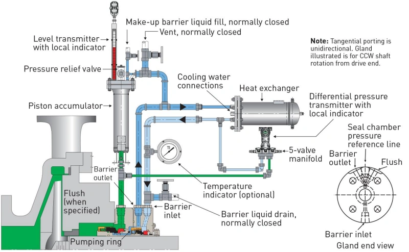
When you need to strictly control leaks of process media, or when the process media itself cannot provide stable lubrication for mechanical seals, a pressurized isolation system should be the first choice.
If your pump handles toxic, flammable, volatile, or environmentally hazardous fluids, a pressurized isolation system should be a top priority for evaluation.
For example, even a small leak of certain chemical fluids can pose safety or environmental risks. By maintaining a positive pressure differential between the isolated fluid and the process fluid, a pressurized isolation system directs leaks during normal operation toward the process side, thereby reducing the release of process fluids into the external environment.
Mechanical seals rely on a thin liquid or gas film between the rotating ring and the stationary ring to reduce friction. If the process medium has poor lubricating properties, the sealing faces may experience friction-induced heating, abnormal wear, or even damage due to failure of the lubricating film.
When pumping media that are prone to vaporization, contain abrasive particles, or are prone to polymerization, consider using a pressurized isolation system so that the two sets of sealing faces are lubricated primarily by a clean isolation medium rather than directly by the process medium.
Tip: For slurries containing solid particles, a pressurized isolation fluid can help reduce the likelihood of particles entering the seal face contact area. However, this does not mean that all slurry pumps must use a pressurized double seal. You still need to verify whether the particle concentration, particle size, tendency to settle, and seal design are suitable for the actual operating conditions.
A pressurized isolation system may also be an appropriate choice when the equipment operates at high pressure, the pressure in the seal chamber fluctuates significantly, or the sealing faces generate a significant amount of frictional heat.
It provides lubrication and cooling to both sets of sealing faces through a controlled circulation of the isolation medium. If the flow rate of the isolation medium is insufficient or its heat dissipation capacity is inadequate, the sealing faces may still overheat. For such operating conditions, you need to evaluate the isolation pressure, circulation flow rate, and heat dissipation capacity simultaneously.
Pressurized isolation systems are not the best choice for all double-face mechanical seals.
1. If your product cannot tolerate the ingress of the isolation medium—such as certain high-purity chemicals, pharmaceuticals, or other processes with strictly controlled product compositions—you should not directly adopt a standard liquid isolation solution.
2. This system is also not recommended if the site cannot maintain a consistent isolation pressure, cannot guarantee a steady supply of the isolation medium, or lacks the necessary monitoring and maintenance capabilities.
| Selection Factor | When to Consider a Pressurized Barrier System | What to Check |
|---|---|---|
| Fluid Hazard | Toxic, flammable, or environmentally hazardous fluids. | Acceptable leakage risk during normal and fault conditions. |
| Fluid Lubricity | Poor lubrication or high vaporization risk. | Whether the barrier fluid provides stable lubrication. |
| Solids & Deposits | Abrasive particles or crystallizing fluids. | Particle properties, deposit risk, and seal design. |
| Pressure & Temperature | Large pressure fluctuations or excessive seal heating. | Pressure differential, circulation, and cooling requirements. |
| Product Purity | Small amounts of barrier fluid can enter the product. | Fluid compatibility and contamination limits. |
| Support System | A reliable barrier pressure supply is available. | Pressure monitoring, fluid replenishment, alarms, and fault response. |

When it is absolutely essential to prevent the process medium from being contaminated by external liquids, while also minimizing leakage into the atmosphere and monitoring the integrity of the internal seal, a non-pressurized buffer system is the preferred choice.
If the medium you are transferring has strict requirements regarding purity, concentration, or chemical composition, a non-pressurized buffer system may be a better option than a standard pressurized liquid isolation system.
In a pressurized isolation system, the pressure is higher than that in the sealed chamber, so a small amount of isolation fluid may enter the process medium through the inner seal. In a non-pressurized buffer system, however, the pressure direction is reversed during normal operation, with the process medium primarily leaking into the buffer space, thereby reducing the risk of external fluid entering the product.
Tip: For certain chemical liquids that require purity to be maintained, if the addition of an external isolation fluid would alter the product’s composition, you should prioritize evaluating a non-pressurized buffer system.
When the process allows for a small, controlled leak at the inner seal and this leak can be safely managed, a non-pressurized buffer system is sufficient; the outer seal serves as a secondary safeguard to minimize media leakage.
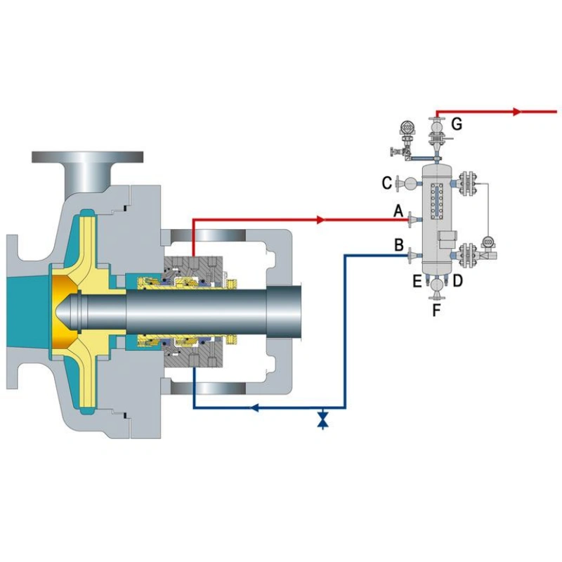
For clean media prone to vaporization, such as light hydrocarbons, API Plan 52 is worth evaluating: if an inner seal leak enters a low-pressure buffer space, it may flash, and the vapor can be routed to a flare or recovery system.
If you want to detect abnormal wear or increased leakage of the inner seal at an early stage, a non-pressurized buffer system also offers advantages.
In a typical API Plan 52 system, the buffer tank can be equipped with a level gauge, a pressure gauge, and corresponding alarm devices. By monitoring the liquid level, pressure, and their trends, you can determine whether the seal may be experiencing abnormalities.
Tip: When leakage from the inner seal increases, the liquid level or pressure in the buffer tank may rise; the specific manifestation depends on whether the process medium is prone to vaporization. If the liquid level in the buffer tank continues to drop, it may be related to leakage from the outer seal.
Compared to systems that require continuous high pressure, the Plan 52 non-pressurized cushioning system does not require a separate pressurization unit. This solution offers advantages when operating conditions are suitable and the goal is to reduce pressurization equipment and related maintenance.
However, non-pressurized does not mean there are no auxiliary components or that the system is maintenance-free: the cushioning fluid must still circulate reliably to ensure lubrication and cooling of the outer seals, and the fluid reservoir, piping, fluid level, temperature, and venting systems must also be inspected regularly.
Unpressurized buffer systems are actually quite sensitive to operating conditions. If your medium contains a lot of solid particles, or tends to aggregate or become sticky, it’s best not to use them. This is because, if the inner seal leaks, these contaminants can easily contaminate the buffer fluid and clog the flow passages, thereby compromising the lubrication and cooling of the outer seal.
If the medium is highly toxic, or if process requirements absolutely prohibit any external leakage, you should also proceed with caution. Non-pressurized systems cannot guarantee that the medium will not leak into the buffer space at all, so you need to calculate in advance whether the outer seal and collection system can handle it.
Step 1: Confirm whether the process medium can tolerate the ingress of a small amount of external barrier fluid.
Step 2: Determine whether the small amount of leakage generated by the internal seal can be safely collected and treated.
Step 3: Check whether the medium is clean, prone to vaporization, and whether it has a tendency to crystallize, polymerize, or deposit.
Step 4: Verify the seal chamber pressure, buffer fluid pressure, operating temperature, and cooling conditions; in particular, consider whether pressure reversal may occur during startup, shutdown, and abnormal operating conditions.
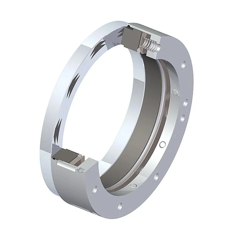
Gas lubrication, liquid lubrication, and dry running are common operating designs for mechanical seals. The key differences among them lie in the medium used by the sealing faces to reduce friction, how the heat generated during operation is controlled, and whether they can operate without liquid lubrication.
| Comparison | Gas-Lubricated | Wet-Lubricated | Dry-Running Design |
|---|---|---|---|
| Lubrication | Gas film. | Liquid film. | Special contact materials or non-contact gas film. |
| Face Contact | Often non-contact. | Often wet-contact. | Contact or non-contact. |
| Main Advantages | Low friction and heat; no liquid lubrication needed. | Effective lubrication and cooling. | Reduced dependence on liquid support systems. |
| Limitations | Requires clean gas, reliable supply, and suitable operating conditions. | Requires stable liquid supply and heat removal. | Limits depend on design, pressure, speed, and dry-running duration. |
| Typical API Plans | Plan 74 | Plans 52, 53A, 53B, 53C, 54 | Plan 72, combined with Plan 75 or 76 as applicable. |
| Suitable Applications | Liquid contamination must be avoided, and clean, stable gas is available. | Stable lubrication and cooling are required, with compatible liquid available. | Containment is needed with reduced reliance on liquid buffer systems. |
| When to Avoid | Unreliable gas supply, gas contamination concerns, or deposit-prone fluids. | Unreliable liquid supply, incompatible fluid, or unacceptable product contamination. | Unverified dry-running capability or inadequate secondary-seal pressure rating. |
| Selection Guide | Choose when liquid contamination must be avoided and stable gas supply is possible. | Choose when reliable lubrication and cooling can be maintained. | Consider when containment must operate without liquid lubrication. |
| Key Considerations | Gas-film stability, gas cleanliness, supply pressure, and shaft speed. | Liquid-film stability, cooling, circulation, and chemical compatibility. | Face materials, validated dry-running limits, and fault-pressure capacity. |
Tip: Gas lubrication and dry running are not entirely distinct categories. Certain non-contact gas-lubricated seals also fall under dry-running designs. Furthermore, API Plans 72, 75, and 76 are supplementary options for specific secondary containment configurations; they are not required for all dry-running seals.

The requirements for double-face mechanical seals vary depending on the equipment and operating conditions. You cannot simply assume that one type—back-to-back, face-to-face, or in-line—is suitable for all equipment.
| Application | Recommended Design | Main Benefits | Key Considerations |
|---|---|---|---|
| Pumps | Pressurized or unpressurized dual seals, based on fluid risk. | Leakage control, lubrication, and cooling. | Check chamber pressure, fluid hazards, and leakage limits. |
| Mixers / Agitators | Specialized dual seals with liquid, gas, or dry-running designs. | Accommodates shaft deflection, axial movement, and low speeds. | Check shaft runout, mounting orientation, and circulation. |
| Slurries | Heavy-duty, wear-resistant seals; pressurized barrier systems if needed. | Reduces particle ingress and clogging. | Check particle properties, face materials, and flushing needs. |
| Hygienic Service | Validated hygienic dual seals with suitable buffer or barrier systems. | Reduces contamination risk and supports cleaning and sterilization. | Check CIP/SIP, dead spaces, and material compliance. |
| High Pressure | Balanced dual seals rated for the required pressure. | Controls face loading and high-pressure leakage risk. | Verify maximum pressure, pressure reversal, and barrier system capacity. |

When selecting a double-face mechanical seal, the characteristics of the process medium, the pressure in the seal chamber, the operating temperature, the shaft speed, the leakage requirements, and the conditions of the auxiliary systems all directly influence the choice of seal design.
The first step in selecting a valve is to thoroughly understand the characteristics of the medium, including its composition, concentration, corrosiveness, viscosity, density, and lubricity. If the medium contains solid particles or is prone to polymerization and coking, it is necessary to determine the particle size, hardness, and deposition characteristics, as these directly affect the choice of face materials, internal structure, and flushing procedures.
Pay close attention to the pressure in the seal chamber (not the pump discharge pressure), and record the minimum, normal, and maximum pressures and temperatures, as well as pressure fluctuations and start-up and shutdown conditions. These data determine the seal’s pressure-bearing capacity and the design of the isolation system. When selecting a pressurized double seal, ensure that the auxiliary system can continuously maintain the specified pressure differential.
Provide the shaft speed (rpm) to evaluate the face sliding speed, heat generation, and the circulation capacity of the auxiliary medium. Also provide the shaft diameter, outer diameter of the shaft sleeve, diameter of the seal chamber, axial installation space, and connection dimensions. If there is significant shaft runout or axial play, the manufacturer must be notified.
Determine whether leakage of the process medium is permitted and whether the barrier medium is allowed to enter the product. When handling toxic, flammable, or hazardous media, pressurized double seals are generally worth evaluating as a priority, as higher barrier pressures can effectively reduce process medium leakage.
Confirm the auxiliary conditions available on-site, including the type of medium, supply pressure, temperature, cleanliness, chemical compatibility, and available flow rate. Also confirm whether cooling, fluid replenishment, and leak detection capabilities are available. Note that buffer fluid is used for non-pressurized double seals, while isolation fluid is used for pressurized double seals.
Specify whether the equipment operates continuously or intermittently, as well as the frequency of starts and stops, since the lubricating film formed during stable operation may not be maintained during low-speed starts or frequent starts and stops. If operating conditions such as brief dry runs, vacuum conditions, frequent forward and reverse rotation, or prolonged standby periods are present, the manufacturer must be notified in advance.
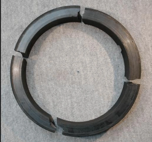
Double-face mechanical seals feature two sets of sealing faces, which enhance leak control and provide additional protection for the seal. However, a double-face design does not necessarily mean the seal will be more durable. If the design, materials, pressure configuration, or auxiliary systems are selected incorrectly, leaks, abnormal wear, or even failure may occur early in operation—even with a high-quality mechanical seal.
| Common Mistake | Cause | Possible Consequences | Correct Approach |
|---|---|---|---|
| 1. Wrong Seal Arrangement | Confusing pressurized (Arrangement 3) and unpressurized (Arrangement 2) dual seals. | Process fluid enters the buffer system, product contamination, or increased leakage risk. | Assess fluid hazards, leakage limits, and contamination risks before selecting the arrangement. |
| 2. Ignoring Pressure Changes | Considering only normal pressure, not startup, shutdown, or pressure reversal. | Abnormal face loading, contamination, overheating, or leakage. | Check minimum, normal, and maximum pressures. Consider Plan 53C for pressure-tracking applications where suitable. |
| 3. Wrong Lubrication Method | Unstable liquid supply, inadequate gas supply, or assuming a standard seal can run dry. | Film breakdown, excessive friction, wear, and overheating. | Select liquid, gas, or dedicated dry-running designs based on service conditions and manufacturer limits. |
| 4. Underestimating Cooling Needs | Ignoring circulation, heat load, and heat dissipation. | Overheating, thermal deformation, film instability, and elastomer aging. | Verify cooling and circulation capacity. Consider external circulation if internal flow is insufficient. |
| 5. Ignoring Material Compatibility | Selecting materials by hardness or temperature rating alone. | Corrosion, wear, O-ring swelling, hardening, or cracking. | Verify compatibility of faces, elastomers, metals, and barrier fluid with the actual chemicals and temperatures. |
| 6. Overlooking Solids and Deposits | Using standard seals for abrasive slurries or ignoring crystallization and buildup. | Abrasive wear, spring sticking, blocked passages, and fluid contamination. | Assess particle size, concentration, hardness, and deposits. Consider slurry-specific seals and wear-resistant faces. |
| 7. Ignoring Shaft Movement | Selecting by shaft diameter alone without checking runout, vibration, or axial movement. | Uneven face loading, wear, instability, and premature leakage. | Verify shaft size, speed, runout, axial movement, and installation space. |
| 8. Wrong Support System | Choosing an API Plan by number alone without assessing pressure, circulation, or compatibility. | Low barrier pressure, lubrication loss, cooling failure, contamination, or leakage. | Select the seal and support system together. Evaluate Plans 52, 53A, 53B, 53C, or 54 as appropriate. |
| 9. Ignoring Startup and Failure Conditions | Overlooking frequent starts, temporary loss of liquid, support-system failure, or inner seal failure. | Dry friction, pressure reversal, poor lubrication, or outer seal overload. | Review startup and fault conditions. Verify dry-running limits, secondary seal pressure ratings, monitoring, and protection. |
Not exactly. A double mechanical seal is a broad category, and a tandem seal is one type of configuration within it, typically consisting of an inner primary seal and an outer secondary seal arranged in an axial configuration.
Barrier fluid is used in pressurized double seals, where the pressure is typically higher than the pressure in the seal chamber; buffer fluid is used in non-pressurized double seals, where the pressure is lower than the pressure in the seal chamber. The pressure relationship between the two determines the possible direction of medium leakage.
It depends on the specific design. Specially designed dry-running seals can operate under specified conditions, but standard liquid-lubricated double seals may overheat and wear out rapidly when lubricant is lacking; they should not be assumed to be capable of dry running.
API Plan 53A is a common pressurized barrier fluid configuration that uses a fluid reservoir pressurized with gas. If pressure fluctuations are significant, cooling requirements are high, or external forced circulation is needed, Plans 53B, 53C, or 54 may also be evaluated based on operating conditions. The specific selection depends on pressure control, cooling requirements, and maintenance conditions.
Yes, but it is necessary to select the appropriate seal configuration, face materials, and auxiliary systems. For slurry applications, attention must be paid to particle abrasion and buildup; for high-pressure applications, the maximum pressure, transient pressure, and the seal’s pressure-bearing capacity must be verified.
It is necessary to confirm the properties of the medium, the pressure in the seal chamber, operating temperature, shaft speed, shaft diameter, shaft runout, allowable leakage rate, product contamination limits, as well as the supply and cooling conditions for the buffer fluid or isolation fluid.
Absolute zero leakage cannot be guaranteed. Actual performance depends on the seal design, operating conditions, and auxiliary systems. Proper selection, continuous monitoring, and regular maintenance help reduce the risk of leakage.
Common causes include incorrect pressure settings, insufficient lubrication, cooling failure, material incompatibility, wear caused by solid particles, excessive shaft runout, and auxiliary system failures.
The key to selecting the right double-face mechanical seal lies in its ability to meet the requirements of the actual operating conditions. Back-to-back, face-to-face, and in-line configurations each have their own characteristics.
When selecting a seal, you should first confirm the characteristics of the process medium, the pressure in the seal chamber, the operating temperature, the shaft speed, and the permissible leakage level, and then choose the appropriate seal configuration, face materials, lubrication method, and auxiliary systems.
If you are unsure about the appropriate configuration, please provide Sakowitz with specific details regarding the medium, pressure, temperature, and equipment parameters so that we can further evaluate suitable configurations and auxiliary systems.
—— We Will Provide You With Professional OEM Solutions.
Whether you require pump bearings, pump valves, mechanical seals, or other custom-engineered components, we support production based on your drawings as well as rapid prototyping.
Please complete the form on the right and upload your technical drawings or specifications. Our engineering team will review your requirements within 24 hours and provide a detailed quotation, application recommendations, and delivery schedule.
Copyright © 2025 Sakowit, All rights reserved.
WhatsApp us