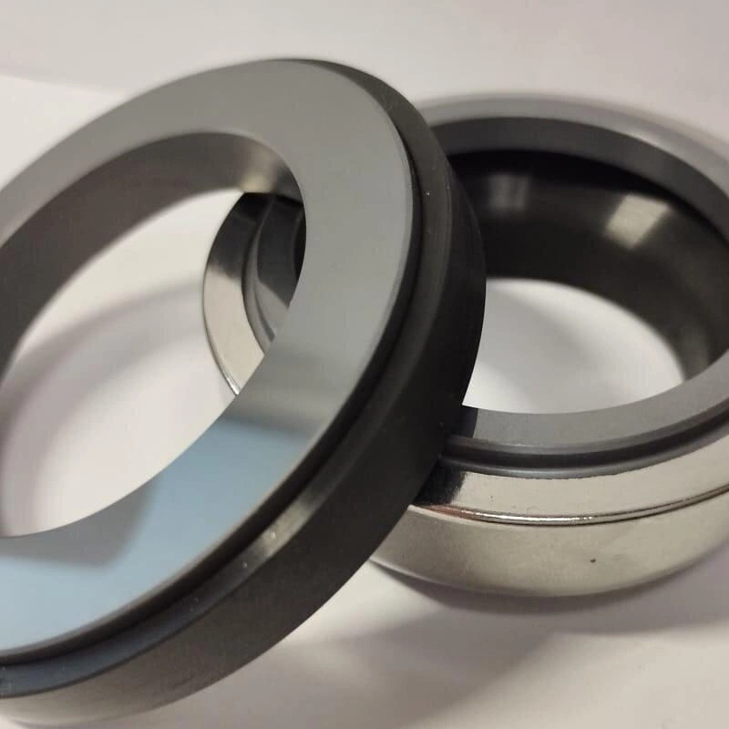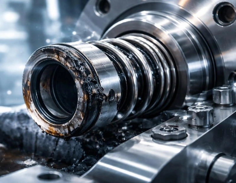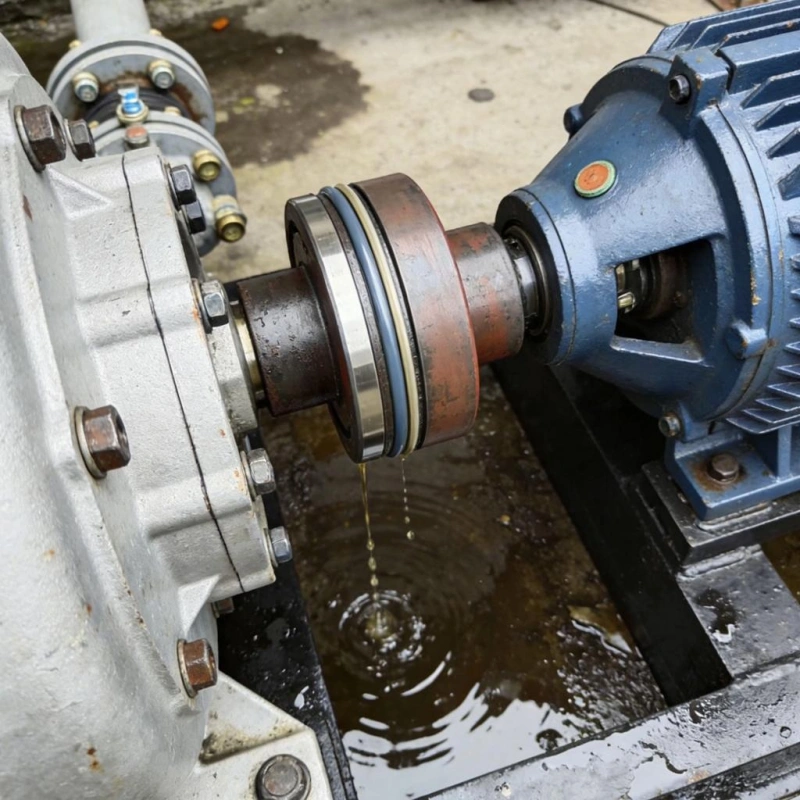

The balance ratio of a mechanical seal is a critical design parameter that determines the force conditions acting on the sealing faces. However, a higher balance ratio is not necessarily better, nor is a lower one.
An excessively high balance ratio may subject the sealing faces to excessive hydraulic closing loads, increasing friction and heat generation. Conversely, an excessively low balance ratio may result in insufficient closing force on the sealing faces, increasing the risk of fluid film instability and leakage.
This article begins with the basic definition and calculation formula for the balance ratio and, using practical dimensional examples, explains how to determine the balance diameter and face diameter and calculate the balance ratio.
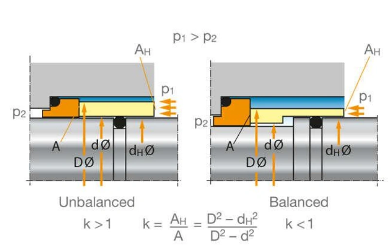
The balance ratio of a mechanical seal refers to the ratio of the hydraulic closing area to the sealing face area. It is an important geometric parameter for measuring the degree of hydraulic balance in a mechanical seal and is primarily used to determine the magnitude of the closing load that the process medium pressure will exert on the sealing faces.
When a mechanical seal is in operation, the process medium inside the pump cavity exerts pressure on the seal rings. When this pressure acts on the back of the seal rings, it generates axial thrust, causing the rotating and stationary rings to move closer together; this force is known as hydraulic closing force.
At the same time, the fluid film pressure between the sealing faces exerts a certain opening force, attempting to separate the two sealing faces. Therefore, a mechanical seal must maintain a reasonable balance between the closing force and the opening force.
The balance ratio is a parameter used to describe the geometric relationship between this hydraulic closing area and the sealing face area.
The balance ratio of a mechanical seal is the ratio of the hydraulic closing area to the sealing face area, expressed as a decimal or a percentage.
To calculate the balance ratio, you must first determine three key dimensions: the outer diameter of the sealing face, the inner diameter of the sealing face, and the balance diameter.
First, determine the area of the annular sealing face based on the outer and inner diameters of the sealing face. Next, determine the hydraulic closing area based on the direction of pressure on the seal structure and the balance diameter. Finally, divide the hydraulic closing area by the sealing face area to obtain the balance ratio.
Tip: The balance ratio is a geometric parameter and does not equal the actual face load. Before calculating, confirm the seal structure, direction of pressure, and effective balance diameter to avoid results being affected by dimensional identification errors.
The balance ratio is expressed as a decimal or a percentage. For example, a balance ratio of 0.80 can also be written as 80%. This means that the hydraulic closing area is equal to 80% of the sealing face area.
From a structural design perspective, the balance ratio is primarily categorized into the following three scenarios:
| Balance Ratio | Seal Type | Basic Meaning |
|---|---|---|
| B < 1 | Balanced Seal | Hydraulic closing area is smaller than the seal face area. |
| B = 1 | Neutral / Critical Balance | Hydraulic closing area equals the seal face area. |
| B > 1 | Unbalanced Seal | Hydraulic closing area is larger than the seal face area. |
Tip: A balance ratio less than 1 does not guarantee that the sealing face will operate stably. It merely indicates that the design reduces the ratio of the hydraulic closing area to the face area. The actual face load is also influenced by factors such as pressure distribution, the effect of the fluid film, and spring force.
The balance ratio directly affects the hydraulic closing force generated by the process pressure on the seal faces. If the closing load is too high, it may increase friction, heat generation, and wear on the seal faces. If the closing load is insufficient, it may prevent the seal faces from maintaining stable contact, increasing the risk of leakage.
You cannot simply assume that a lower balance ratio is always better. When making a selection, you must consider the operating pressure, the properties of the medium, the lubrication conditions, and the seal design all at the same time.
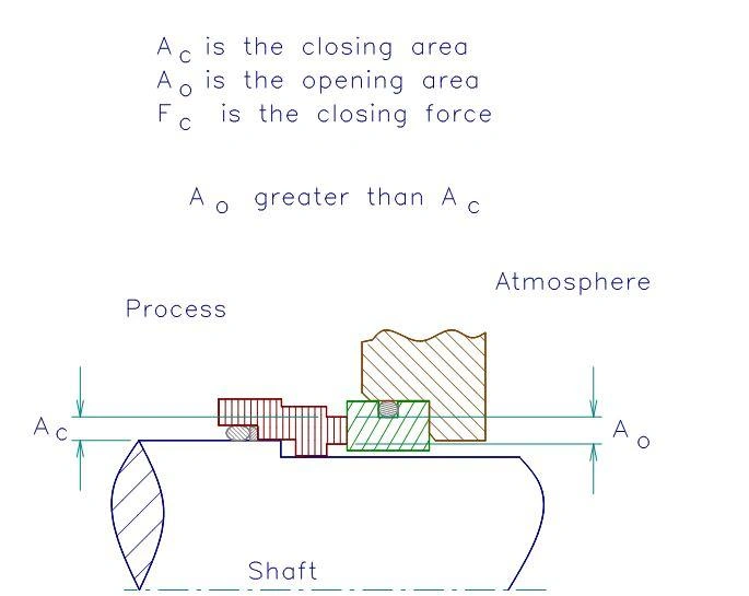
When calculating the balance ratio for a mechanical seal, the most critical step is not simply applying a formula, but correctly identifying three dimensions: the balance diameter, the outer diameter of the seal face, and the inner diameter of the seal face.
The seal face is the precision-ground surface where the rotating ring and stationary ring come into close contact to form the sealing interface. It is annular in shape and therefore has two basic dimensions.
Face Outside Diameter: The outermost diameter of the annular region of the seal face.
Face Inside Diameter: The innermost diameter of the annular region of the seal face.
It is important to note that the face outside diameter and face inside diameter refer to the boundaries of the annular seal face that actually participate in the sealing process, not the maximum outside diameter and minimum inside diameter of the entire seal ring component.
The balance diameter is the dimension most prone to error when calculating the balance ratio. It is not simply the shaft diameter, nor is it necessarily equal to the outer diameter of the shaft sleeve; rather, it is the effective diameter determined by the hydraulic action boundary within the seal structure.
You can think of it as the dividing diameter on the back of the seal ring between the area subjected to process medium pressure and the low-pressure area.
The direction of pressure on a mechanical seal affects how the hydraulic closing area is determined; therefore, before calculating the balance ratio, you must first confirm whether the process medium applies pressure from the inner diameter side or the outer diameter side of the seal face.
The process medium pressure acts primarily on the outside diameter side of the sealing face. For common designs, the hydraulic closing area is defined by the annular region between the face outside diameter (Do) and the balancing diameter (Db).
With all other dimensions held constant, the larger the balancing diameter, the smaller the hydraulic closing area, and the lower the balance ratio.
The process medium pressure acts primarily on the inner diameter side of the sealing face. For common designs, the hydraulic closing area is determined by the annular region between the balancing diameter (Db) and the inner diameter of the sealing face (Di).
With all other dimensions remaining constant, the larger the balancing diameter, the larger the hydraulic closing area, and the higher the balancing ratio.
If you have a cross-sectional drawing of a mechanical seal, you can identify the dimensions using the following method:
| Dimension | Measurement Location | Main Function |
|---|---|---|
| Do | Outer boundary of the actual seal face contact area. | Defines the seal face outer diameter. |
| Di | Inner boundary of the actual seal face contact area. | Defines the seal face inner diameter. |
| Db | Effective boundary of the hydraulic closing area. | Defines the balance diameter. |
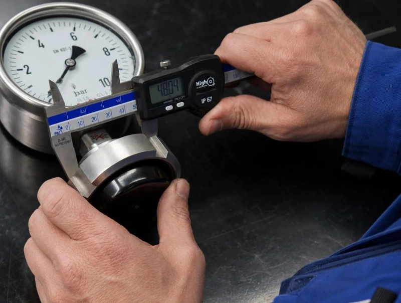
Now that you understand the definition of the balance ratio and the three key diameters, the next step is to perform the calculations using actual dimensions. You don’t need complex equipment or specialized software; as long as you can identify the outer diameter, inner diameter, and balance diameter of the sealing faces, you can perform the basic calculations.
Suppose you have a mechanical seal, and its drawings provide the following dimensions:
Example Seal Dimensions
| Measurement | Symbol | Dimension |
|---|---|---|
| Seal Face Outer Diameter | Do | 50 mm |
| Seal Face Inner Diameter | Di | 40 mm |
| Balance Diameter | Db | 45 mm |
Note: The dimensions above are hypothetical values used to demonstrate the calculation process and do not represent actual factory test data.
You need to confirm that this is a structure subjected to pressure on the outer diameter side. The process medium applies pressure from the outside of the sealing face, and the equilibrium diameter lies between the outer and inner diameters of the face.
The sealing face is an annular area, not a complete circle. You need to consider an annular working surface with an outer diameter of 50 mm and an inner diameter of 40 mm.
Based on these dimensions, the calculation yields:
Sealing face area
706.86 mm²
Determined by an outer diameter of 50 mm and an inner diameter of 40 mm
This value represents the geometric area of the actual annular working surface between the rotating ring and the stationary ring, and serves as the basis for subsequent calculations of the balance ratio.
Next, calculate the hydraulic closing area.
Since this is a structure subjected to pressure on the outer diameter side, the hydraulic closing area is located between the outer diameter of the end face and the balance diameter.
In this example:
Outer boundary: 50 mm.
Inner boundary: 45 mm.
The annular region formed by these two diameters is the hydraulic closing area to be calculated in this example.
The calculation result is:
Hydraulic Closing Area
373.06 mm²
Determined by an outer diameter of 50 mm and an inner diameter of 45 mm
We now have two key pieces of data:
| Calculation Item | Area |
|---|---|
| Hydraulic Closing Area | 373.06 mm² |
| Seal Face Area | 706.86 mm² |
Comparing the hydraulic closing area with the sealing face area yields:
Final calculation result
0.528
52.8%
The geometric balance ratio is less than 1.
This means that the hydraulic closing area accounts for approximately 52.8% of the sealing face area.
From a geometric perspective, this constitutes a balanced mechanical seal design. It reduces the closing force exerted by process pressure on the sealing faces by decreasing the hydraulic closing area.
Tip: The figure of 52.8% does not imply that the actual sealing force on the faces is limited to a fixed proportion, nor does it guarantee that the seal will operate stably. The actual face load is also influenced by the pressure distribution of the fluid film, spring load, and operating conditions.
After calculating the balance ratio, you must also understand how the three diameters affect the result—this is especially critical when changing seals or reviewing supplier designs:
Face outer diameter: If all other dimensions remain constant, a change in this dimension simultaneously affects both the face area and the hydraulic closing area, causing the balance ratio to change accordingly.
Face inner diameter: This directly determines the effective face area. In a structure where the outer diameter side is under pressure, the larger the inner diameter, the smaller the face area, and the lower the balance ratio typically becomes.
Balance diameter: Again, for structures where the outer diameter side is under pressure, the larger the balance diameter, the smaller the hydraulic closing area, and the lower the balance ratio.
The key difference between balanced and unbalanced mechanical seals lies in the closing load generated when hydraulic pressure acts on the sealing faces.
An unbalanced mechanical seal is a sealing structure with a relatively large hydraulic closing area. The pressure of the process medium acting on the sealing rings generates a significant axial closing force, which keeps the rotating ring and stationary ring in close contact.
This type of seal features a relatively simple design and does not require special balancing steps or specific pressure-bearing area designs to significantly reduce the hydraulic closing load.
A balanced mechanical seal reduces the effective hydraulic closing area generated by process pressure by adjusting the geometry of the sealing rings, thereby lowering the hydraulic closing load on the sealing faces.
A common design approach involves incorporating balancing steps on the seal rings or related components to adjust the position of the dynamic auxiliary seal and alter the area subject to hydraulic forces.
The differences between the two designs are primarily reflected in aspects such as hydraulic closing load, pressure adaptability, frictional heat generation, and structural complexity.
| Comparison | Unbalanced Seal | Balanced Seal |
|---|---|---|
| Hydraulic Closing Load | Relatively higher. | Relatively lower. |
| Balance Ratio | Usually ≥ 1. | Usually < 1. |
| Pressure Capability | Better suited to lower-pressure service. | Better suited to higher-pressure service. |
| Face Friction | May increase significantly at higher pressure. | Proper design helps reduce friction. |
| Friction Heat | Higher overheating risk at elevated pressure. | Helps reduce heat generation. |
| Face Wear | May accelerate under high face loading. | Helps reduce excessive wear. |
| Design Complexity | Relatively simple. | More complex. |
| Manufacturing Cost | Generally lower. | Generally higher. |
| Typical Applications | Low-pressure, general pump service. | Medium- to high-pressure and demanding applications. |
The balanced design primarily affects friction, temperature rise, and pressure-bearing capacity:
Friction Control: In unbalanced designs, the end-face load surges sharply after pressure increase, resulting in high friction; in balanced designs, the load increase is suppressed by reducing the hydraulic closing area, allowing for better friction control.
Temperature Rise and Wear: Heat generated by friction that cannot be dissipated will destroy the fluid film and exacerbate wear. Balanced designs can reduce load and mitigate risks, but they cannot replace proper flushing and cooling designs.
Pressure-Carrying Capacity: This is the core distinction. Under high-pressure conditions, unbalanced designs cannot withstand the load, whereas balanced designs have lower hydraulic loads and better adaptability. However, do not rely solely on the balance ratio; you must also verify the strength of the seal ring, auxiliary seals, and the manufacturer’s pressure limits.
If your pump operates at low pressure, the fluid provides good lubrication, and operating conditions are relatively stable, an unbalanced mechanical seal should be your first choice.
For example, standard industrial circulation pumps, low-pressure transfer pumps, and some conventional liquid transfer equipment can use an unbalanced design, provided they meet the manufacturer’s pressure and speed limits.
When your pump needs to handle liquids at higher pressures, or when an unbalanced seal might be subjected to excessive face-to-face closing loads, a balanced mechanical seal is a more viable option to consider.
Common applications include: High-pressure centrifugal pumps: The seal chamber pressure is high, requiring control of the hydraulic face-to-face closing load.
Chemical process pumps: The fluid pressure and operating conditions require the seal to have good stability.
High-temperature liquid pumps: These require control of friction-induced heat at the sealing faces to prevent further increases in thermal load.
Continuous-duty equipment: These applications aim to reduce excessive face loads, thereby lowering the risk of wear and maintenance demands.
When selecting mechanical seals, the balance ratio, liquid film pressure, and spring load are three concepts that are easily confused. While they are all related to the force conditions on the sealing faces, their physical meanings are entirely different.
The balance ratio is the ratio of the hydraulic closing area to the sealing face area. It reflects how the seal structure uses geometric dimensions to control the closing action generated by the process medium pressure.
You can think of it as a fundamental design parameter for seal structures. For example, two mechanical seals may have the same face dimensions, but due to differences in the position of the dynamic O-ring, their balance diameters may differ, resulting in different balance ratios.
Tip: The balance ratio itself is not the actual face load, nor is it the face pressure. Even if two seals have the same balance ratio, the hydraulic closing loads they actually bear may differ if their operating pressures are different.
A fluid film is an extremely thin layer of fluid formed between the rotating and stationary rings. When a mechanical seal is in operation, a small amount of process medium enters the space between the two seal faces, forming the fluid film necessary for lubrication and cooling.
The fluid film reduces direct contact between the faces and also generates fluid pressure. This pressure exerts an opening force on the seal faces, causing them to tend to separate.
Fluid film pressure is not simply a replica of the pressure in the entire seal chamber. It is influenced by the geometry of the sealing faces, the thickness of the fluid film, the viscosity of the medium, the rotational speed, and the pressure
Spring loading refers to the mechanical force generated by a spring through its elastic deformation. Its primary function is to push the rotating ring, keeping it in contact with the stationary ring, and to compensate for wear on the sealing faces or changes in axial position.
Spring loading is particularly important when the pump is at rest prior to startup. At this time, without the dynamic fluid film generated during normal operation, the spring helps keep the sealing faces in contact.
For thrust-type mechanical seals, the spring typically provides axial closing force through the rotating ring assembly. As the sealing faces wear, the spring can compensate for a certain amount of displacement by extending or compressing axially.
Although all three parameters affect the forces acting on the sealing faces, their functions are not the same.
| Comparison | Balance Ratio | Fluid Film Pressure | Spring Load |
|---|---|---|---|
| Basic Nature | Geometric parameter. | Fluid pressure. | Mechanical force. |
| Main Source | Seal geometry. | Fluid between seal faces. | Spring deformation. |
| Main Function | Controls hydraulic closing area. | Provides face-opening force. | Provides face-closing force. |
| Changes with Pressure? | Normally constant. | Changes with operating conditions. | Not directly determined by process pressure. |
| Affected by Speed? | No direct effect. | May be affected. | No direct effect. |
| Effect on Face Friction | Indirect. | Directly affects face force balance. | Directly affects face loading. |
| Design Basis | Balance diameter and face dimensions. | Fluid film and operating conditions. | Spring stiffness and compression. |
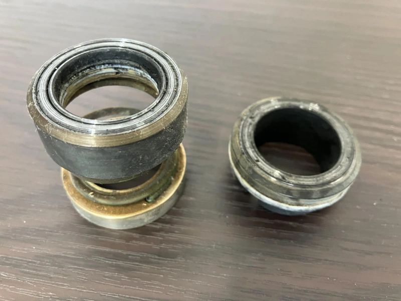
The balance ratio of a mechanical seal is not merely a geometric design parameter; it also affects the actual stress state of the sealing faces and, in turn, influences friction, temperature rise, wear, and leakage.
Face load refers to the actual load acting on the sealing faces of the rotating and stationary rings. It determines the degree of contact between the two faces and is a key factor affecting the operating condition of a mechanical seal.
The balance ratio primarily influences the hydraulic closing load generated by the process medium pressure by altering the hydraulic closing area.
For seal structures with identical conditions and the same pressure direction:
High balance ratio: The hydraulic closing area is relatively large, and the closing force generated by the process pressure is typically stronger.
Low balance ratio: The hydraulic closing area is relatively small, and the closing force generated by the process pressure is typically weaker.
Tip: The hydraulic closing load is not equal to the final face load. During actual operation, the closing force provided by springs or bellows, as well as the opening force generated by the face liquid film, must also be taken into account.
Face friction is the friction generated between the rotating ring and the stationary ring due to their relative motion.
During normal operation, an extremely thin fluid film typically exists between the two faces. This fluid film reduces direct contact between the solid surfaces while bearing part of the load.
When the hydraulic closing load is excessive, the sealing faces may be subjected to high contact loads. If the fluid film cannot adequately share this load, friction between the sealing faces may increase.
Friction between the sealing faces generates heat, which must be dissipated through the process medium, the seal rings, and the associated cooling or flushing systems.
If the heat generated by face-to-face friction exceeds the system’s heat dissipation capacity, the temperature in the sealing area may continue to rise.
Excessively high face temperatures may lead to the following issues:
Leakage in mechanical seals is closely related to the state of the fluid film between the sealing faces.
The balance ratio indirectly affects this equilibrium by altering the hydraulic closing load.
When the closing load is too high:
The sealing faces may be subjected to excessive contact pressure, resulting in an overly thin fluid film, increased friction, and rising temperatures. If thermal deformation or wear occurs on the sealing faces, the originally stable sealing condition may be disrupted, ultimately leading to leakage.
When the closing load is insufficient:
The lifting force of the fluid film may exceed the effective closing capacity of the faces, increasing the face clearance and leading to increased leakage.
Therefore, a lower balance ratio is not necessarily better, nor is a higher one. You need to ensure that, under actual operating conditions, the seal has sufficient closing capacity while maintaining a stable fluid film.
For a more intuitive understanding, refer to the comparison below:
| Performance | Excessive Closing Load | Insufficient Closing Load |
|---|---|---|
| Face Contact | Excessive contact load. | Seal faces may separate. |
| Friction | May increase significantly. | Depends on fluid film and face contact. |
| Temperature | May continue to rise. | May remain normal but local overheating can occur. |
| Fluid Film | May become too thin or unstable. | May fail to maintain stable sealing. |
| Wear | May accelerate. | Abnormal face contact or damage may occur. |
| Leakage | May increase due to overheating, deformation, or wear. | May increase directly. |
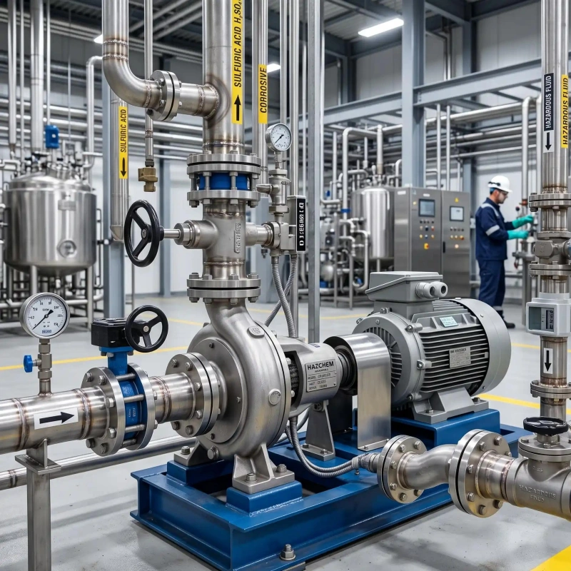
The balance ratio of a mechanical seal cannot be determined solely based on the pump’s operating pressure. Even if two seal sets have the same balance ratio, their actual operating performance may differ significantly depending on the pumped medium, lubrication conditions, and operating mode.
Operating pressure is the primary factor to consider when selecting a balance ratio. The pressure of the process medium acts on the seal assembly, generating a hydraulic closing force.
For unbalanced mechanical seals, the hydraulic closing area is relatively large. As the pressure in the seal chamber increases, the hydraulic closing load on the sealing faces also increases.
Fluid properties affect the formation and stability of the fluid film between the sealing faces.
The fluid film is a thin layer of fluid between the rotating and stationary rings, primarily providing lubrication and cooling. Different media have varying viscosities, lubricity, and flow characteristics, and therefore have different effects on the sealing faces.
If the medium can form a stable fluid film between the sealing faces, this generally helps reduce direct contact between the faces. However, you must still ensure that the fluid film does not vaporize due to rising temperatures or falling pressure.
For media with insufficient lubricating ability, boundary contact is more likely to occur between the sealing faces—meaning the fluid film cannot completely separate the two sealing surfaces.
In this case, the risk of friction and temperature rise may increase. You must comprehensively consider the face materials, surface conditions, and auxiliary flushing conditions; you cannot rely solely on adjusting the balance ratio to resolve the issue.
High viscosity does not necessarily mean better lubrication conditions. Viscosity affects liquid film formation, fluid shear, and heat dissipation from the sealing faces. For high-viscosity media, you must also pay attention to cold-start performance, fluid flow resistance, and fluid supply within the seal chamber.
Vapor pressure is the pressure at which a liquid forms vapor at a specific temperature. It is an important parameter for evaluating the stability of the liquid film in a mechanical seal.
If the local pressure near the seal faces is lower than the saturated vapor pressure of the medium at the current temperature, the liquid may vaporize.
When a liquid rapidly vaporizes due to a drop in pressure, this phenomenon is called flashing.
Flash vaporization can disrupt the liquid film on the sealing faces, deteriorating lubrication and cooling conditions, which in turn leads to increased friction, elevated temperatures, and damage to the sealing faces.
For abrasive or corrosive media, selecting the right material is essential; even the most reasonable balance ratio cannot prevent material failure:
Abrasive media (slurries, wastewater, ore slurry): Particle scouring + abrasive wear; the end face cannot withstand this. The key considerations are whether the face material is sufficiently hard, the particle size and solid concentration, and whether the flushing method can effectively remove the particles; the balance ratio is not a decisive factor.
Corrosive media: Chemical compatibility must be verified for all metal components, springs, and elastomers. Once corrosion sets in, the seal structure will disintegrate, springs will fail, and O-rings will swell, rendering the seal immediately unusable.
Transient operating conditions refer to unstable operating conditions that occur for a short period during equipment startup, shutdown, pressure changes, or operational state transitions.
You need to pay special attention to the following situations:
| Transient Condition | Potential Effect on Mechanical Seal | Balance Ratio Selection Focus |
|---|---|---|
| Pump Startup | Pressure, speed, and fluid film gradually develop. | Check startup pressure and initial closing capability. |
| Pump Shutdown | Fluid film disappears and pressure may redistribute. | Check closing capability at standstill. |
| Sudden Pressure Increase | Hydraulic closing load rises rapidly. | Verify face load at maximum pressure. |
| Sudden Pressure Drop | Fluid may vaporize and film stability may decrease. | Check minimum pressure and flashing risk. |
| Frequent Start-Stop Cycles | Seal faces experience repeated load and temperature changes. | Check elastic compensation and thermal-cycle capability. |
| Sudden Flow Loss | Seal chamber may lose normal lubrication and cooling. | Check lubrication and dry-running risk. |
The following examples of common applications will illustrate how you should make an initial assessment.
| Application | Preferred Seal Design | Key Selection Factors |
|---|---|---|
| Low-Pressure Clean Water Pump | Balanced or unbalanced seal. | Pressure, cost, and operating stability. |
| High-Pressure Centrifugal Pump | Balanced seal. | Control hydraulic closing load. |
| High-Temperature Hot Water Pump | Balanced design worth evaluating. | Vapor pressure, film stability, and elastomer temperature limits. |
| Light Hydrocarbon Pump | Select based on pressure and vaporization risk. | Vapor pressure, flashing, and face lubrication. |
| High-Viscosity Fluid Pump | Select based on actual fluid-film conditions. | Flowability, startup behavior, and heat dissipation. |
| Solids / Slurry Pump | Select based on solids characteristics. | Wear-resistant materials, flushing, and particle control. |
| Corrosive Chemical Pump | Select based on material compatibility. | Metals, elastomers, and seal face materials. |
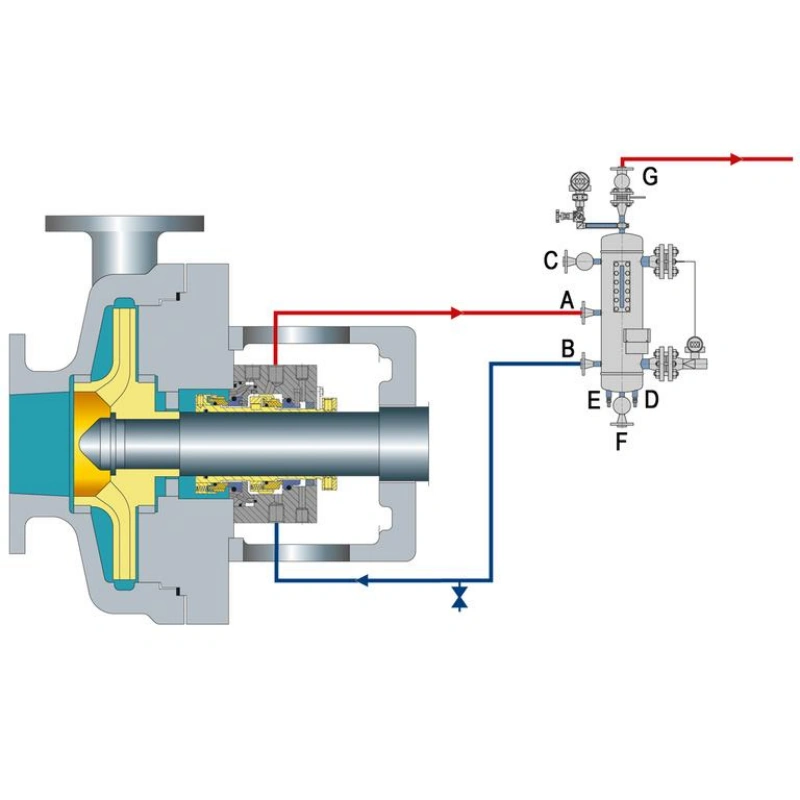
When selecting a mechanical seal balance ratio, you also need to check for reverse pressure differentials. This is especially true for double-face mechanical seals, where the inner and outer seals may be subjected to different pressures; therefore, you cannot simply use the same balance ratio to determine whether both sets of seals are suitable.
A reverse pressure differential refers to a pressure relationship on either side of the seal that is the opposite of normal design conditions.
For example, a mechanical seal may be originally designed for process medium pressure to act from the side of the seal face’s outer diameter. When pressure on the other side suddenly increases, or when pressure on the process side decreases, the seal may be subjected to pressure in the opposite direction of the original design.
You need to clearly distinguish between two concepts:
The balance ratio is designed and calculated based on the normal direction of pressure on the seal. When the pressure direction reverses, the original hydraulic closing force may change or even transform into an opening force.
This means that the hydraulic load, which originally helped keep the faces closed, may no longer function in the same way under reverse pressure.
A dual-face mechanical seal consists of an inner seal and an outer seal, with an independent fluid space between the two seal sets.
Based on the pressure conditions in this space, common designs are classified into two types:
Arrangement 2: Unpressurized double mechanical seal, where the pressure of the buffer fluid between the two sets of seals is lower than the pressure in the pump’s seal chamber.
Arrangement 3: Pressurized double mechanical seal, where the pressure of the isolation fluid between the two sets of seals is higher than the pressure in the pump’s seal chamber.
For double-face mechanical seals, you cannot simply calculate the balance ratio for a single set of seals and assume that it applies to the entire seal assembly.
We recommend that you check the following separately:
| Check Item | Inner Seal | Outer Seal |
|---|---|---|
| Main Fluid Contact | Process fluid or barrier fluid. | Buffer or barrier fluid. |
| Pressure Source | Seal chamber and intermediate chamber. | Intermediate chamber and atmospheric side. |
| Balance Ratio | Determined by inner seal geometry. | Determined by outer seal geometry. |
| Main Risks | Process leakage and pressure reversal. | Barrier fluid leakage and poor lubrication. |
| Key Checks | Pressure direction and reverse-pressure capability. | Pressure, temperature, and circulation conditions. |
The pressure relationship in a double-ended mechanical seal is not always constant. Startup, shutdown, and system switching can all alter the pressure differential between the process side and the intermediate chamber.
You need to pay special attention to the following situations:
| Operating State | Possible Issue | Key Check |
|---|---|---|
| Before Pump Startup | Barrier fluid pressure may not be established. | Verify support system startup conditions. |
| Pump Startup | Process pressure rises rapidly. | Check inner seal pressure response. |
| Normal Operation | Barrier fluid pressure may fluctuate. | Check pressure control and circulation. |
| Pump Shutdown | Process pressure drops rapidly. | Check for pressure reversal. |
| System Depressurization | Intermediate chamber may remain pressurized. | Verify reverse-pressure capability. |
| Cooling Period | Trapped liquid may expand or change pressure. | Check pressure risk from trapped fluid. |
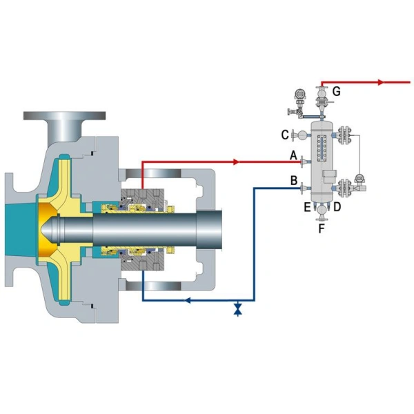
When calculating the balance ratio for a mechanical seal, even if you use the correct calculation method, it does not guarantee that the final result will be accurate. This is because the balance ratio depends not only on dimensional measurements but also on the seal design, the direction of pressure, and whether the hydraulic boundary is correctly identified.
The balance diameter is one of the dimensions most prone to error when calculating the balance ratio.
It defines the boundaries of the hydraulic closure area but is not necessarily equal to the shaft diameter, the outer diameter of the shaft sleeve, or the outer diameter of the seal ring.For common push-ring mechanical seals, the balance diameter is related to the effective sliding seal position of the dynamic O-ring.
The situation is even more complex for metal bellows seals. Their effective balance diameter is related to the pressure-acting area of the bellows; the arithmetic mean of the bellows’ inner and outer diameters cannot simply be taken as the balance diameter.
The seal face area should be determined based on the actual annular working surface involved in the seal, rather than on the overall external dimensions of the entire seal ring assembly.
For example, a seal ring may have mounting flanges, locating steps, and non-contacting areas. These parts do not necessarily constitute the effective sealing face.
If you treat the maximum outer diameter of the entire part as the face diameter, or include non-working areas in the face area, it will affect the final calculation results.
This is another issue that can easily lead to calculation errors.
The hydraulic closure areas for outside-diameter and inside-diameter pressurization are different; therefore, different diameter combinations are used when determining the hydraulic closure area.
If you apply a previously used calculation method without first confirming the direction of pressure on the medium, you may obtain an incorrect balance ratio.
Mechanical seal dimensions are expressed in millimeters or inches.
If you mix different units in the same calculation, even if all dimensions are correct, the final result may contain significant errors.
In addition, caliper measurements, seal ring wear, and component machining tolerances can also affect dimensional accuracy.
For smaller seal faces, even minor measurement errors can affect the final balance ratio, especially when the balance diameter is close to the face diameter.
This is a critical misconception in mechanical seal selection.
The balance ratio reflects the geometric relationship between the hydraulic closing area and the face area, but it does not equal the actual face closing load.
During actual operation, the forces acting on the sealing faces are also influenced by the following factors:
Geometric calculations can only describe the basic dimensional relationships of the seal structure; they cannot accurately predict the actual state of the fluid film between the sealing faces.
The fluid film is a thin layer of fluid formed between the rotating and stationary rings, serving to lubricate and cool the sealing faces.
Its state is influenced by the medium’s viscosity, temperature, pressure, rotational speed, and the structure of the sealing faces.
In actual operation, mechanical seals are not completely rigid structures.
When the sealing faces are subjected to pressure and frictional heat, slight elastic or thermal deformation may occur.
Furthermore, the fluid film pressure is not uniformly distributed across the entire sealing face. Pressure may vary at different locations, and the actual lifting action depends on the pressure distribution across the entire sealing face.
A double-face mechanical seal consists of an inner seal and an outer seal; these two seal sets may have different face dimensions, balance diameters, and pressure conditions.
If you calculate the balance ratio for only one of the seal sets, you cannot determine whether the entire double-face seal assembly is suitable based on that alone.
Furthermore, a reverse pressure differential may alter the original direction of the hydraulic force, causing the actual stress state to deviate from normal design conditions.
Common risks include:
No, it is not. 70% is merely a geometric balance ratio and cannot be applied to all pumps. You also need to consider the seal chamber pressure, the properties of the medium, the face materials, and the operating conditions.
Yes. A balance ratio greater than 1 typically indicates an unbalanced mechanical seal, where the hydraulic closing area is greater than the sealing face area.
No. You also need to know the inner diameter, outer diameter, and balance diameter of the sealing faces. The shaft diameter alone is not sufficient to determine the balance ratio.
No. The balance ratio is a geometric parameter, while the pressure rating is the maximum pressure the seal is designed to withstand. The two are not interchangeable.
It cannot be done simply by replacing the O-ring. The balance ratio depends on the overall structure and the effective pressure boundary; arbitrarily changing the position of the O-ring may cause leakage or structural failure.
Generally, no. As long as the seal face dimensions, balance diameter, and structure remain unchanged, replacing the seal face material will not alter the geometric balance ratio.
Either millimeters (mm) or inches (inch) may be used, but all diameters must use a consistent unit; mixing units is not permitted.
Yes. The hydraulic balance ratio of a metal bellows seal can also be evaluated, but the calculation must be based on the effective compressed area of the bellows and the effective balance diameter specified by the manufacturer; the dimensional definitions for standard push-ring seals cannot be directly applied.
A correct understanding of the balance ratio for mechanical seals is a crucial step in ensuring proper force distribution on the sealing faces, reducing friction-induced heat, and extending service life. The balance ratio depends not only on the inner diameter, outer diameter, and balance diameter of the sealing faces but is also closely related to the seal design, the direction of pressure, and actual operating conditions.
Sakowitz specializes in mechanical seals and sealing solutions for pumps. Through proper structural design, material selection, and balance ratio optimization, we help you reduce the risk of leakage, improve equipment reliability, and meet the sealing requirements of various industrial applications.
—— We Will Provide You With Professional OEM Solutions.
Whether you require pump bearings, pump valves, mechanical seals, or other custom-engineered components, we support production based on your drawings as well as rapid prototyping.
Please complete the form on the right and upload your technical drawings or specifications. Our engineering team will review your requirements within 24 hours and provide a detailed quotation, application recommendations, and delivery schedule.
Copyright © 2025 Sakowit, All rights reserved.
WhatsApp us