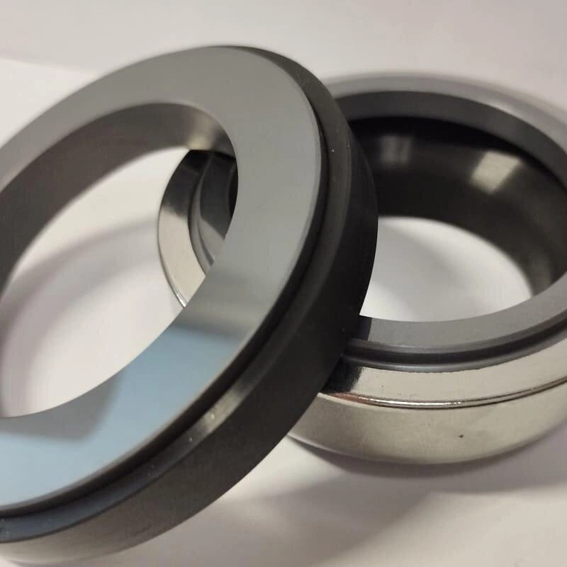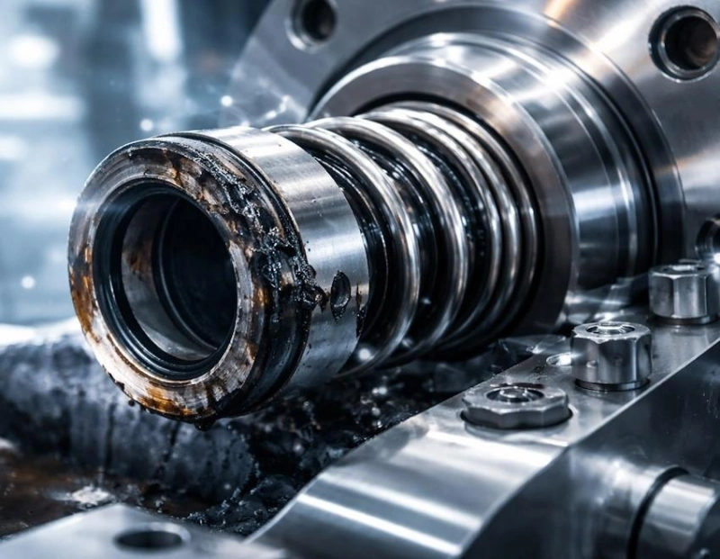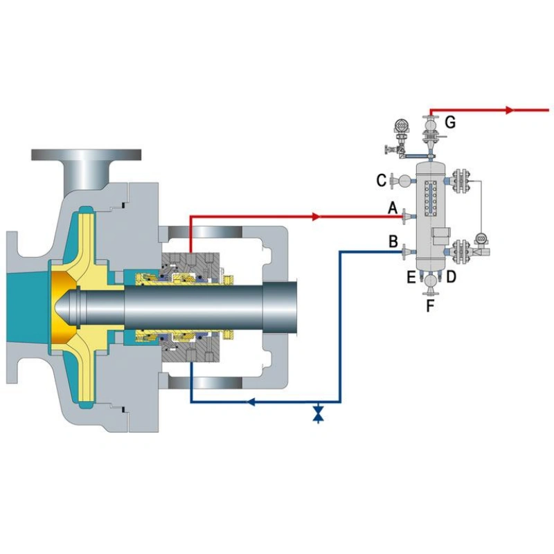

Proper installation of a mechanical seal is key to preventing leaks, ensuring stable operation, and extending service life. Installation isn’t simply a matter of inserting a new seal into the pump; it also requires inspecting the condition of the shaft and seal chamber, confirming the working length, and correctly installing the rotating and stationary rings. Additionally, the flushing, quenching, and isolation systems must be connected in accordance with design requirements.
This article follows the sequence of on-site procedures to thoroughly cover pre-installation preparations, component installation, dimensional adjustments, auxiliary system connections, leak testing, and startup inspections. It also reviews common causes of leaks immediately after installation to help you avoid pitfalls and improve the operational reliability of pumps and rotating equipment.
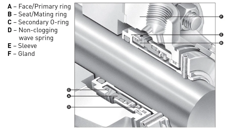
Before installing a mechanical seal, you must verify the seal model, design type, installation drawings, and the technical specifications provided by the manufacturer. Do not begin installation based solely on the appearance or dimensions of the old seal. Even if the new and old seals look similar, their internal structures, installation lengths, spring settings, and material configurations may differ.
First, you need to determine what type of seal you are dealing with. Mechanical seals can be classified in various ways, so you cannot determine all of their installation requirements based on a single name alone.
Common types include:
| Seal Type | Main Features | Key Installation Checks |
|---|---|---|
| Component Seal | Individual components supplied separately for on-site assembly. | Installation dimensions, ring positions, and spring working length. |
| Cartridge Seal | Main components pre-assembled as one unit. | Installation position, fastening, and setting device removal sequence. |
| Single Seal | One set of primary seal faces. | Face orientation, secondary seals, and operating conditions. |
| Double Seal | Two sets of seal faces. | Seal arrangement, barrier fluid, or buffer fluid system. |
| Pusher Seal | Uses a dynamic secondary seal to move axially and compensate for wear. | O-ring position, shaft sleeve surface, and sliding clearance. |
| Non-Pusher Seal | Uses metal bellows or similar structures for axial compensation. | Bellows orientation, installation position, and compression. |
Tip: These categories are not mutually exclusive. For example, a cartridge-type seal can feature a double-face design or incorporate a metal bellows design.
Installation drawings are a crucial reference for determining part locations, dimensional relationships, and installation requirements. Different models of mechanical seals may have different structural dimensions and installation specifications, even if their external shapes appear similar.
Pay close attention to the following information:
Seal Model/Part Number: Ensure it matches the purchase order and equipment requirements.
Shaft Diameter: Confirm that the fit dimensions match those of the pump shaft and shaft sleeve.
Installation Length: The axial dimension after installation must meet design requirements.
Rotating and stationary rings: Ensure correct position, orientation, and fit—do not install them backwards
Set dimensions: Specific positions/dimensions that must be precisely aligned during installation
Material configuration: Sealing faces, O-rings, and metal components must be suitable for the operating conditions
Connection specifications: Locations and specifications of connections for flushing, quenching, and isolation systems
Drawings primarily show the location, dimensions, and structural relationships of parts, while installation instructions provide further details on specific installation requirements, tool usage, and precautions.
Pay close attention to the following:
Installation sequence: Confirm the correct installation orientation and sequence for each part.
Installation tools: Confirm whether specialized installation tools are required.
Positioning devices: For cartridge seals, confirm when to engage and disengage the positioning clips or set tabs.
Lubrication requirements: Confirm which assembly lubricants the manufacturer permits.
Special installation restrictions: Note whether the manufacturer has specified any special requirements regarding rotation direction, axial position, spring compression, or installation clearance.
Confirming that the seal model is correct does not necessarily mean it is suitable for the current pump equipment. You also need to verify that the mechanical seal matches the actual design of the pump.
We recommend focusing on the following checks:
| Check Item | What to Confirm |
|---|---|
| Pump Model | Pump model and manufacturer. |
| Shaft Diameter | Shaft or sleeve dimensions. |
| Seal Chamber | Chamber design and installation space. |
| Seal Type | Confirm the seal design meets equipment requirements. |
| Operating Pressure | Verify pressure is within design limits. |
| Operating Temperature | Verify compatibility with material and design limits. |
| Shaft Rotation | Confirm rotation direction matches the seal design. |
| Auxiliary System | Check compatibility of flush, quench, or barrier systems. |
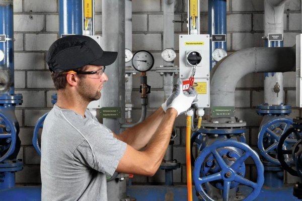
Four tasks must be completed before installing a mechanical seal: isolating the equipment, depressurizing the system, draining the medium, and cleaning and decontaminating the equipment. These four steps are interrelated but cannot be substituted for one another.
First, you must stop the pump and reliably isolate the equipment from all possible sources of power and media.
Isolating the equipment involves more than just turning off the pump’s start button; it also includes disconnecting the power supply, closing the relevant pipeline valves, and preventing other equipment or automated control systems from starting up accidentally.
In the second step, you need to verify that the pump body, seal chamber, and associated piping have been completely depressurized.
Depressurization refers to the safe release of residual pressure from inside the equipment into a designated system through designed venting, drainage, or depressurization devices.
Tip: Do not relieve pressure by directly loosening flanges, gland packs, or pipe fittings. Use the pressure relief and discharge connections provided in the equipment design, and direct the medium into a safe collection or disposal system.
Step 3: You also need to drain any residual liquid from the pump casing, seal chamber, and associated piping.
Drainage involves removing liquid from inside the equipment to prevent sudden leakage during disassembly or contamination of new mechanical seal components.
You should pay special attention to the following locations:
Pump Casing: Drain the liquid through the designated drain port.
Seal Chamber: The seal chamber is the area that houses the mechanical seal and provides its operating space.
Suction and Discharge Lines: Check for accumulated liquid at the lowest points of the piping, as well as near elbows and valves.
Auxiliary Piping: Inspect the flushing fluid, quench fluid, isolation fluid, and buffer fluid lines to confirm whether there is still pressure or residual fluid present.
Draining the equipment does not mean it is clean. Chemical residues, corrosive liquids, flammable substances, or toxic materials may still be present on the pump body, in the seal chamber, and on the inner walls of the piping.
Decontamination is the process of reducing the presence of harmful substances inside and on the surfaces of equipment through proper cleaning, flushing, or other treatment methods, thereby ensuring the equipment meets the specified safety requirements for maintenance.
The specific cleaning method depends on the properties of the conveyed medium.
| Fluid Type | Main Risks | Safety Precautions |
|---|---|---|
| Corrosive Chemicals | Chemical burns and material corrosion. | Select cleaning fluids compatible with the chemicals. |
| Flammable Liquids | Fire and explosion. | Control ignition sources and use gas detection when required. |
| Toxic Fluids | Poisoning through inhalation or skin contact. | Follow safety procedures and use toxic gas detection when required. |
| High-Temperature Fluids | Burns and thermal shock. | Confirm the equipment has cooled to a safe working temperature. |
| Abrasive Slurries | Solid residue and mechanical damage. | Remove solids from the seal chamber and pipelines. |
After completing isolation, pressure relief, drainage, and cleaning, you must also perform a final safety check.
The key concept here is the “Zero-Energy State,” which means that all energy sources in the equipment that could cause harm have been isolated, released, or controlled in accordance with regulations.
It is recommended that you focus on verifying the following items:
| Check Item | What to Confirm |
|---|---|
| Electrical Isolation | Power is disconnected, locked out, and verified de-energized. |
| Mechanical Isolation | Rotating parts are stopped and stored mechanical energy is controlled. |
| Pressure Verification | Pump, seal chamber, and connected piping are fully depressurized. |
| Drainage Verification | Residual liquid has been drained from equipment and piping. |
| Temperature Verification | Equipment has reached a safe working temperature. |
| Chemical Decontamination | Hazardous process fluid has been removed as required. |
| Gas Testing | Required gas testing is completed based on fluid and work hazards. |
| Work Authorization | Required maintenance permits and safety approvals are in place. |
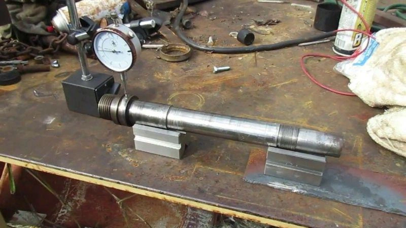
Before installing a mechanical seal, you must carefully inspect the mechanical condition of the pump shaft, shaft sleeve, and seal chamber. Even if the model, material, and dimensions of a new mechanical seal are exactly correct, wear, bending, or abnormal runout of the pump shaft can cause uneven stress on the sealing faces and an unstable lubrication film, ultimately leading to leakage or premature failure.
A shaft sleeve is a replaceable sleeve installed on the outside of the pump shaft. In some pumps, the shaft sleeve provides a mounting and mating surface for the mechanical seal while protecting the pump shaft from wear and corrosion.
During inspection, you should pay close attention to the following issues:
Scoring: Check for visible longitudinal scratches or grooves on the shaft surface.
Corrosion: Check for signs of rust, pitting, or chemical corrosion.
Fretting: Check for wear and surface damage caused by repeated micro-movements at the mating surfaces.
Burrs: Check for protrusions or sharp edges at the shaft shoulders, keyways, and edges.
Wear: Check the O-ring contact areas for grooves, wear, or dimensional changes.
Surface Damage: Check for dents, deformation, or other issues that could affect the installation fit.
Tip: Different sealing designs have slightly different requirements for the shaft surface. Do not assume that a shaft sleeve is suitable for installation based solely on visual inspection of the surface smoothness.
Shaft runout refers to the radial or axial deviation of the measurement point relative to a fixed reference point when the shaft rotates.
When installing a mechanical seal, the primary concern is radial runout—that is, the radial deviation of the measurement point as the shaft rotates.
End play refers to the phenomenon where the pump shaft moves back and forth along its centerline.
Simply put, the shaft may not only wobble from side to side but also move back and forth along its length.
The rotating and stationary rings of a mechanical seal must maintain proper axial contact. Although the springs or bellows inside the seal can provide some axial compensation, this compensation capacity is limited.
The seal chamber is the area inside the pump where the mechanical seal is installed and where it operates.
The dimensions, surface condition, and geometric accuracy of the seal chamber directly affect whether the mechanical seal can be installed correctly and whether the rotating and stationary rings can maintain stable operating conditions.
If you discover abnormalities in the shaft surface, runout, axial play, or the seal chamber, you must first determine the source of the problem before deciding whether to proceed with installation.
| Inspection Issue | Possible Cause | Recommended Action |
|---|---|---|
| Shaft Surface Scratches | Installation damage or long-term wear. | Assess sleeve repair or replacement. |
| Shaft Surface Corrosion | Fluid corrosion or material incompatibility. | Review material compatibility and consider replacement. |
| Excessive Radial Runout | Bent shaft, eccentric sleeve, or bearing wear. | Inspect the shaft, sleeve, and bearings. |
| Excessive Axial Movement | Bearing damage or incorrect axial positioning. | Inspect bearings and positioning components. |
| Damaged Seal Chamber Bore | Corrosion, wear, or foreign object damage. | Assess repair or replacement. |
| Uneven Gland Mounting Surface | Corrosion, deformation, or residue. | Clean and inspect surface flatness. |
| Incorrect Locating Fit | Dimensional deviation, machining defects, or wear. | Check drawings and correct mating dimensions. |
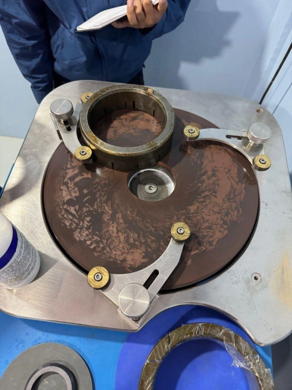
Before installing a mechanical seal, you need to prepare a clean work environment and appropriate installation tools, and ensure that the sealing faces and auxiliary seals are in good condition. Mechanical seals are precision components; in particular, the sealing faces of the rotating and stationary rings have been precision-ground and are highly sensitive to dust, particles, scratches, and oil contamination.
First, you need to prepare installation tools that are compatible with the mechanical seal’s design. The tools must not only meet installation requirements but also be kept clean to prevent scratching the shaft sleeve, sealing faces, or other precision components during operation.
Common tools include:
| Tool | Main Use | Key Notes |
|---|---|---|
| Allen Keys | Install set screws and fasteners. | Use the correct size to avoid screw damage. |
| Torque Wrench | Tighten bolts to the specified torque. | Follow manufacturer torque requirements. |
| Soft-Jaw Pliers | Hold components during installation. | Do not clamp precision seal faces. |
| Installation Sleeve | Guides seals over shaft shoulders and keyways. | Protect O-rings from cuts and scratches. |
| Micrometer | Measure shaft and related dimensions. | Check tool accuracy and calibration before use. |
| Dial Indicator | Check shaft runout and mechanical condition. | Ensure the measuring stand is securely mounted. |
| Lint-Free Cloth | Clean seal faces and component surfaces. | Avoid leaving fibers or particles. |
| Non-Metallic Tools | Assist with elastomer and precision-part installation. | Reduce scratching and surface damage. |
Seal faces are precision-machined surfaces where the rotating ring and stationary ring come into close contact to form a sealing interface. A very thin liquid film forms between them, which serves to lubricate and dissipate heat while controlling media leakage.
The rotating ring and stationary ring must maintain a good face-to-face fit. If dust, metal particles, or other foreign matter enters the space between the two faces, it may cause localized scratches or wear, preventing the faces from forming a stable liquid film as intended.
In addition, oils from fingers, cleaning agent residues, and fibers can also contaminate the sealing surfaces. Therefore, you should not assume that a face meeting installation requirements simply because it has no visible scratches.
Tip: Do not use acetone, alcohol, or other industrial solvents indiscriminately to clean all mechanical seals. Different face materials, coatings, auxiliary seals, and designs may have varying chemical compatibility. You should always prioritize following the manufacturer’s cleaning instructions.
Elastomers are a class of materials capable of elastic deformation. They are commonly used in the secondary sealing sections of mechanical seals to help prevent media leakage through the clearance between mating parts.
Common materials include:
NBR: Nitrile rubber, commonly used for mineral oils and certain general industrial media.
FKM: Fluorocarbon rubber, which generally offers good heat resistance and resistance to a variety of chemical media.
EPDM: Ethylene-propylene-diene monomer rubber, commonly used for water, hot water, and certain chemical media.
FFKM: Perfluoroelastomer, typically used in environments with high chemical and temperature demands.
PTFE: Polytetrafluoroethylene, a fluorinated polymer with excellent chemical stability; it is not a rubber elastomer in the traditional sense.
When installing a mechanical seal, assembly lubricants are required for certain auxiliary sealing components and sliding mating surfaces to facilitate smooth installation and reduce friction and damage.
However, it is important to understand a key distinction: assembly lubricants are not the same as the lubricant used during the operation of a mechanical seal.
Assembly lubricants are primarily used during the installation process to help components such as O-rings pass through mating surfaces, preventing distortion, scratches, or tears during installation. Lubrication during the operation of a mechanical seal, on the other hand, relies primarily on the liquid film between the sealing faces or other lubricants specified by the design.
After selecting the correct lubricant, you must also determine where to apply it and how much to use.
Not all parts of a mechanical seal require lubrication. Incorrect use of lubricant may actually interfere with the proper operation of the sealing faces.
| Installation Area | Lubrication Required? | Key Notes |
|---|---|---|
| O-Ring | Follow manufacturer requirements. | Use lubricant compatible with the elastomer. |
| Shaft Sleeve Surface | Depends on seal design. | Avoid damaging dynamic O-rings during installation. |
| Static Secondary Seal | Follow manufacturer requirements. | Ensure proper seating in the groove. |
| Rotating Face | Do not apply grease unless specified. | Keep the face clean and follow manufacturer instructions. |
| Stationary Face | Do not apply grease unless specified. | Avoid grease and particle contamination. |
| Spring | Usually no extra lubrication required. | Do not alter the spring surface condition. |
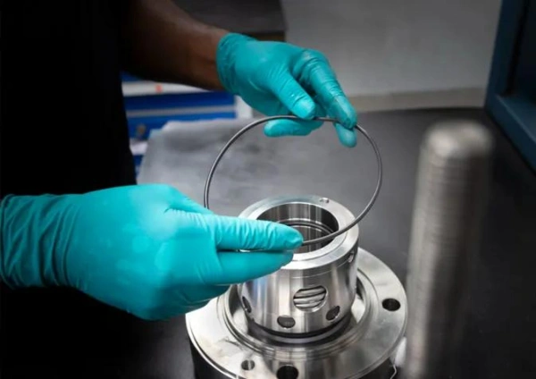
When installing a mechanical seal, the installation positions, mounting methods, and operating requirements for the stationary and rotating components differ. You must follow the installation drawings provided by the manufacturer to install the stationary ring in the designated position first, and then install the rotating ring assembly onto the pump shaft or shaft sleeve.
Stationary Components refer to sealing parts that do not rotate with the pump shaft after installation, including the stationary ring, stationary ring seat, and related auxiliary sealing components. The stationary ring is generally installed in a designated position on the seal gland or in the seal chamber.
Rotating Components refer to sealing parts that rotate with the pump shaft; they typically include the rotating face, springs, spring seats, drive mechanisms, and related auxiliary sealing components.
Tip: The structures of different mechanical seals vary. For example, pusher-type seals typically use dynamic O-rings to provide axial compensation, whereas non-pusher-type seals may use metal bellows for compensation. The specific installation methods for these two types are not entirely interchangeable.
The stationary component is installed in the designated position within the sealing gland or sealing chamber. Before installation, you must verify that the stationary ring model, installation orientation, auxiliary seals, and positioning features match those shown in the drawings.
Check the sealing surface of the stationary ring for scratches, cracks, chipped edges, or contamination. Also, ensure that the stationary ring seat, O-ring, and installation groove are clean.
Tip: Pay special attention to the orientation of the stationary ring. Some stationary rings have a specific installation orientation or positioning mechanism and must not be installed upside down. You must confirm the orientation of the sealing surface and the positioning method based on the manufacturer’s drawings.
If the stationary ring uses an O-ring seal, verify that the O-ring’s material, size, and installation position are correct.
Avoid twisting, stretching, or squeezing the O-ring during installation. If the manufacturer permits the use of assembly lubricant, apply a small amount of compatible lubricant to the specified contact points to help the stationary ring slide smoothly into the installation groove.
When installing the stationary ring, use the manufacturer’s recommended installation tool or a suitable press-fit tool to ensure the stationary ring enters the installation position smoothly in the axial direction.
Note that the press-fit force should be applied to the stationary ring seat or the force-bearing area specified by the manufacturer, rather than directly to the precision-ground end face.
After installing the static ring, you must verify the following:
Rotating assemblies are typically mounted on the pump shaft or shaft sleeve and are connected to the shaft via set screws, drive rings, spring assemblies, or other design methods.
Before installation, you must verify the orientation of the rotating ring’s end face, the spring position, and the drive mechanism based on the drawings.
In particular, for push-ring and non-push-ring mechanical seals, their axial compensation mechanisms differ, so the installation direction cannot be determined solely by appearance.
The rotating assembly typically needs to be slid axially onto the pump shaft or shaft sleeve.
If the shaft sleeve has keyways, threads, shaft shoulders, or other sharp edges, forcing the rotating assembly directly past these areas may cut the O-rings or damage other auxiliary seals.
You must control the axial position of the rotating assembly according to the installation drawings.
For component seals, the position of the assembly is typically determined based on specified installation dimensions to provide a correct foundation for setting the spring’s working length later.
Some mechanical seals use set screws to secure the rotating assembly to the shaft sleeve, while other products employ different fastening mechanisms.
The sealing faces of the rotating and stationary rings are typically precision-ground.
Lapping is a precision machining process that ensures the sealing faces achieve a high degree of flatness and surface quality to meet the operational requirements of mechanical seals.
The working fluid film between the sealing faces is extremely thin; even minute particles, scratches, and localized damage can affect the proper mating of the faces.
After installing the rotating and stationary rings, you must also verify that the positions and alignment of the two sets of components are correct.
Alignment refers to the correct relative positions and geometric relationships between related parts as specified in the design. For mechanical seals, incorrect positioning or misalignment can result in uneven contact between the sealing faces.
Be sure to check the following:
| Inspection Item | What to Check | Why It Matters |
|---|---|---|
| Stationary Face Position | Ensure the stationary face is correctly seated. | Prevent tilting or loosening. |
| Rotating Face Position | Check that the rotating face is at the specified axial position. | Ensure correct operating position. |
| Face Orientation | Verify correct rotating and stationary face orientation. | Ensure proper face alignment. |
| O-Ring Condition | Check for twisted or damaged O-rings. | Prevent secondary seal leakage. |
| Anti-Rotation Pin | Check correct pin positioning. | Prevent unintended stationary face rotation. |
| Drive Mechanism | Check that the drive components are properly engaged. | Ensure the rotating face turns with the shaft. |
| Component Clearance | Check for abnormal interference between components. | Prevent mechanical binding after installation. |
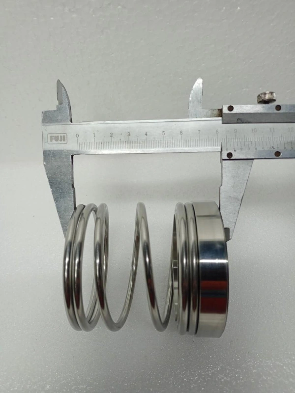
When installing a modular mechanical seal, you must accurately set the working length and spring compression according to the manufacturer’s drawings. These two parameters affect the closing force between the rotating and stationary rings and are critical to ensuring the proper operation of the mechanical seal.
Working Length refers to the distance between two axial reference surfaces specified by the manufacturer when the mechanical seal is in its prescribed installation state. Measurement references may vary by model; for example, they may include the gland mounting surface, the spring seat, or a designated position on the rotating assembly.
Spring Compression refers to the axial deformation of the spring after it is compressed from its specified reference length to its installed working state. By providing a certain amount of elastic force, the spring helps maintain the proper sealing contact between the rotating and stationary rings.
Before adjusting a modular mechanical seal, you must first locate the installation drawings for the corresponding model to confirm the manufacturer-specified dimensions.
These dimensions are used to determine the correct axial position of the rotating assembly relative to the stationary assembly or the equipment reference plane.
You should pay particular attention to the following:
| Inspection Item | What to Confirm |
|---|---|
| Seal Model | Matches the actual seal being installed. |
| Working Length | Specified installation dimension from the manufacturer. |
| Setting Dimension | Reference points and distances specified in the drawing. |
| Spring Arrangement | Single spring, multiple springs, or other compensation design. |
| Shaft Position | Required shaft position during measurement. |
| Installation Tolerance | Dimensional tolerances specified by the manufacturer. |
| Fixing Method | Set screws, drive collar, or other fixing components. |
Tip: The working lengths of different seal models cannot be directly interchanged. Even if two mechanical seals have the same shaft diameter, their spring designs, face geometries, and mounting references may be completely different.
For modular seals that require on-site positioning, you can determine the position of the rotating assembly by following the measurement methods specified by the manufacturer. The typical procedure is as follows:
The spring compression directly determines the face sealing force. Keep the following points in mind when adjusting:
Don’t under-compress: Insufficient sealing force can lead to leaks during startup or when pressure fluctuates
Do not over-compress: This causes excessive end-face friction, increased temperature, and rapid wear; in severe cases, it can directly damage the spring or the compensation mechanism.
For multi-spring seals, check each spring individually: Ensure every spring is properly seated, not jammed or misaligned, otherwise uneven stress will be applied to specific areas.
Do not rely on feel: Simply pushing the push ring or feeling the end face is insufficient to determine whether the compression is correct; you must follow the dimensions specified in the drawings.
Before securing the rotating assembly, you need to double-check the working length, spring condition, and axial position.
| Inspection Item | What to Check | Potential Consequences |
|---|---|---|
| Working Length | Verify dimensions against the drawing. | Abnormal face loading. |
| Spring Compression | Ensure compression is within the specified range. | Leakage or excessive wear. |
| Shaft Position | Confirm the specified operating position. | Incorrect installation dimensions. |
| Rotating Assembly Position | Check alignment with the setting marks. | Incorrect spring operation. |
| Spring Movement | Check for abnormal sticking. | Reduced compensation capability. |
| Set Screws | Verify correct positioning and tightening torque. | Assembly movement or shaft sleeve damage. |
“Setting Devices” refer to temporary positioning components installed on cartridge seals, such as positioning clamps, positioning tabs, and centering tabs. They are used to hold the seal in a predetermined position or to help the seal assembly maintain proper centering during installation.
Before installation, you need to understand the functions and common designs of positioning devices. Common positioning devices include:
| Positioning Device | Main Function | Action After Installation |
|---|---|---|
| Setting Clips | Hold the seal assembly in its preset position. | Usually must be completely removed. |
| Centering Tabs | Keep the seal assembly centered. | Remove as instructed by the manufacturer. |
| Setting Plates | Hold or restrict the seal assembly position. | Some must be moved and secured in a non-operating position. |
| Eccentric Washers | Change the positioning state through rotation. | Release and lock according to the design requirements. |
When installing a cartridge seal, the first thing to do is resist the urge to remove the positioning devices prematurely; keep them in the initial state specified by the manufacturer.
First, check the positioning components: ensure the positioning clamps, positioning plates, and screws are not loose, deformed, or missing.
Next, inspect the assembly itself: check the gland, shaft sleeve, drive ring, and auxiliary seals for any impact damage, and verify that the gland gasket is properly positioned
During installation, gently slide the assembly along the shaft or shaft sleeve, aligning it with the positioning marks specified in the drawings.
Make sure not to reverse the connection directions: the flushing, drain, quench, and isolation fluid ports must correspond to the piping.
Do not disassemble any internal components of the cartridge seal throughout the process, and do not forcefully pry open the positioning clamps or tamper with the preset positions. Do not compromise the precision pre-adjusted by the manufacturer.
Once the seal assembly is in place, you need to properly connect the seal gland to the mounting surface of the pump’s seal chamber.
Check that the gland is properly aligned with the seal chamber mounting surface, and ensure that the gasket is not misaligned or extruded.
Install the gland bolts or nuts in their corresponding positions. Following the manufacturer’s installation instructions, you may first tighten them by hand or leave them slightly loose to allow for final positioning of the pump shaft and impeller.
Tighten the gland bolts gradually and evenly, following the manufacturer’s specified tightening sequence.
A cross-pattern tightening method may be used, in which tightening force is applied progressively in a diagonal sequence to prevent the gland from tilting.
Check that the gland is flush against the seal chamber mounting surface, confirm that the bolts are tightened to specification, and ensure there is no noticeable misalignment.
Do not take this step—securing the shaft position and drive ring—lightly. Although the working length of a cartridge seal is pre-adjusted at the factory, it must still be aligned to the correct axial position once installed on the pump.
First, determine the shaft’s axial position: the impeller position, bearing clearance, and axial clearance all affect the shaft’s final position, so these must be adjusted according to equipment requirements.
Before removing the positioning device, ensure the shaft does not move freely; otherwise, if the shaft shifts as soon as the positioning device is loosened, the seal’s operating conditions will be completely altered.
The drive ring is used to transmit torque to the seal; it must be locked securely to the shaft and rotate with it.
If securing with set screws, strictly follow the manufacturer’s specified screw positions, tightening sequence, and torque values. Do not tighten them arbitrarily—if they are too loose, the seal will slip; if they are too tight, they will damage the shaft.
The positioning device must be released only after the sealing gland, drive assembly, and pump shaft have been secured in accordance with the manufacturer’s specifications.
Follow these steps:
Step 1: Verify that installation and securing are complete.
Step 2: Identify the specific configuration of the positioning device.
Step 3: Release the positioning device according to the manufacturer’s instructions.
Step 4: Verify that the positioning device has been fully released.
Step 5: Store the reusable positioning device.
Removing the positioning device does not mean that the installation is completely finished. You still need to check whether the sealing components are in proper working order.
| Inspection Item | What to Confirm | Inspection Purpose |
|---|---|---|
| Gland Bolts | Ensure gland bolts are tightened evenly. | Prevent gland misalignment. |
| Drive Collar | Ensure the drive collar is securely fastened. | Prevent rotating assembly slippage. |
| Setting Clips | Remove all clips designated for removal. | Prevent rotating interference. |
| Setting Plates | Move and secure plates in the specified position. | Prevent contact with the shaft sleeve. |
| Shaft Position | Confirm the shaft is in the specified operating position. | Maintain correct installation. |
| Seal Connections | Verify gland port orientation against the drawing. | Ensure correct auxiliary piping connections. |
| Shaft Rotation | Confirm the shaft rotates freely as required. | Check for abnormal mechanical interference. |
After installing the mechanical seal, you must also properly connect and inspect the seal support systems. These systems are used to improve lubrication and cooling conditions at the sealing faces, control the temperature, pressure, and medium conditions within the seal chamber, and help ensure the stable operation of the mechanical seal.
Before connecting the piping, you first need to understand how these three systems work. Most importantly, you need to distinguish where they act on the seal and what medium they use.
A flush system introduces a liquid into the seal chamber or a designated area of the seal to dissipate frictional heat, improve face lubrication, reduce media buildup, or control the temperature within the seal chamber.
The flush fluid can come from the pump discharge, an external fluid supply system, or other engineered fluid sources, depending on the seal design and auxiliary piping configuration.
Quenching involves introducing steam, nitrogen, or other specified media to the atmospheric side of the mechanical seal to improve environmental conditions on the outer side of the seal.
It does not directly enter the process-side sealing faces between the rotating and stationary rings but acts on the atmospheric side of the seal.
The barrier fluid system is primarily used in pressurized double-face mechanical seals.
The barrier fluid is the liquid located between the inner and outer sets of sealing faces; its pressure typically needs to be higher than the pressure of the process medium in the seal chamber to control the direction of leakage during normal operation.
Tip: The barrier fluid system is different from the buffer fluid system. Buffer fluid is typically used in non-pressurized double-face seals, where its pressure is lower than the pressure on the process side of the seal chamber; the two should not be confused.
The flushing system is connected to the process side of the mechanical seal—that is, the side closest to the pump chamber. During installation, you must verify the source, flow direction, and connection location of the flushing fluid based on the specified API Piping Plan.
Common flushing configurations include:
| API Plan | Operating Principle | Typical Applications |
|---|---|---|
| Plan 11 | Routes pump discharge fluid through an orifice into the seal chamber. | Flushing and cooling for clean process fluids. |
| Plan 23 | Circulates seal chamber fluid through a cooler using an internal pumping device. | Cooling high-temperature liquids. |
| Plan 32 | Injects clean external flush fluid into the seal chamber. | Fluids containing solids, prone to crystallization, or contamination. |
Quick-cooling systems are typically connected to the atmospheric side of the mechanical seal—that is, the side facing away from the process medium inside the pump.
The main difference between a quick-cooling system and a flushing system is that flushing primarily acts on the process side of the seal area, while quick-cooling primarily improves the environmental conditions on the outside of the seal.
API Plan 62 is a common external quick-cooling solution that introduces a specified medium to the atmospheric side of the seal via external piping.
Common quench media include:
Steam: Used in certain high-temperature hydrocarbon applications or conditions prone to coking or the formation of deposits on the outer side.
Nitrogen: Used in applications requiring inert gas protection or control of the external environment.
Water: Used in certain applications requiring cooling or cleaning of the outer side of the seal.
Barrier fluid is a specialized liquid that fills this space. Its primary functions are to lubricate and cool the sealing faces, while also controlling the direction of medium leakage by maintaining a pressure higher than that on the process side.
Common barrier fluid systems include:
| API Plan | System Design | Main Features |
|---|---|---|
| Plan 53A | Pressurized reservoir. | Nitrogen directly pressurizes the barrier fluid reservoir. |
| Plan 53B | Bladder accumulator. | A bladder separates the pressurizing gas from the barrier fluid. |
| Plan 53C | Piston accumulator. | A piston transfers pressure and can follow process pressure changes. |
| Plan 54 | External pressurized circulation system. | Uses an external pump and supply system to circulate barrier fluid. |
Both are used between the two sets of faces in a double-face mechanical seal, but they differ in terms of pressure relationships and intended functions.
| Comparison | Barrier Fluid | Buffer Fluid |
|---|---|---|
| Typical Seal Arrangement | Pressurized dual seal. | Unpressurized dual seal. |
| Common API Plans | Plans 53 and 54. | Plan 52. |
| Pressure Relationship | Higher than process pressure. | Lower than process pressure. |
| Main Functions | Lubrication, cooling, and pressure isolation. | Lubrication, cooling, and leakage collection. |
| Normal Leakage Direction | Barrier fluid flows toward the process side. | Process fluid may enter the buffer fluid. |
| Typical Applications | Applications requiring strict external leakage control. | Applications requiring inner seal leakage monitoring and collection. |
After completing the piping connections, you’ll also need to conduct a systematic inspection. Don’t just verify that the pipe fittings are tightened; you must also ensure that the entire auxiliary system operates normally in accordance with design specifications.
We recommend focusing on the following items:
Priming refers to filling auxiliary systems to a specified liquid level before starting up the equipment.
Venting refers to removing unwanted gas from piping, coolers, storage tanks, and seal chambers.
If air is present in the flushing or isolation fluid lines, it may cause circulation instability, resulting in insufficient lubrication and cooling of the sealing faces. In certain high-temperature operating conditions, trapped gas may also affect local temperature control.
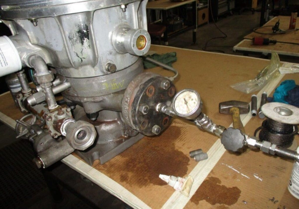
After installing the mechanical seal, you’ll need to reassemble the pump housing, check that the pump shaft rotates freely, and perform a leak test in accordance with the equipment and seal manufacturers’ specifications.
After installing the mechanical seal, you must reassemble the equipment step by step in accordance with the pump’s assembly drawings and the manufacturer’s instructions.
During reassembly, pay special attention to the following areas:
Ensure that all mating surfaces of the pump casing are clean and that any residue from old gaskets has been removed.
Check that the gland bolts are tightened in the specified order and to the correct torque.
If the bearing housing was disassembled during maintenance, ensure that the bearings, bearing end covers, and related positioning components have been installed correctly. Improper bearing assembly may cause unstable shaft operation, which can affect the performance of the mechanical seal.
If the coupling was disassembled, reinstall it according to the equipment specifications and check the alignment between the motor shaft and the pump shaft.
Ensure that all bolts, nuts, and fasteners have been installed correctly.
Tip: When reassembling, do not focus solely on the mechanical seal itself. Any assembly errors related to the pump shaft, bearings, or seal gland may affect the final operating results.
The Shaft Rotation Check involves inspecting the pump shaft and related rotating components—either manually or using the manufacturer’s specified method—to determine whether there is any abnormal binding, mechanical interference, or assembly resistance.
Incorrect installation of the mechanical seal, abnormal positioning of the shaft sleeve, interference with the drive ring, or incorrect bearing assembly can all increase the rotational resistance of the pump shaft.
A Static Leak Test involves checking for leaks at seals and joints under specified medium and pressure conditions while the equipment is not in normal rotational operation.
Static leak tests are primarily used to inspect the following locations:
The sealing area between the mechanical seal and the pump shaft or shaft sleeve.
The auxiliary sealing area between the stationary ring and the seal gland.
The joint between the seal gland and the pump casing.
The pump casing, flanges, and other relevant connection points.
The connection points of the isolation fluid or buffer fluid system for double-face seals.
The purposes of static and dynamic leak tests are not entirely the same.
Static tests primarily examine the sealing condition when the equipment is not rotating, while dynamic tests are used to evaluate the performance of mechanical seals under actual rotating conditions.
| Comparison | Static Leak Test | Dynamic Leak Test |
|---|---|---|
| Equipment Condition | No normal rotational operation. | Pump or test equipment rotates normally. |
| Main Purpose | Check static seals and connections. | Evaluate sealing performance during operation. |
| Key Checks | Static leakage and pressure retention. | Leakage, temperature, vibration, and operating stability. |
| Main Factors | Test pressure, fluid, and installation condition. | Speed, pressure, temperature, lubrication, and operating conditions. |
| Applicable Stage | Before startup or during specified maintenance acceptance tests. | Equipment trial runs or dedicated performance tests. |
After completing the test, you need to determine whether the seal meets the requirements based on the seal type, process medium, and manufacturer’s specifications.
In standard liquid-lubricated mechanical seals, a very thin liquid film exists between the two sealing faces during operation. Therefore, not all visible liquid phenomena should be interpreted as seal failure, nor should any visible leakage be considered acceptable.
You need to distinguish between the following situations:
| Observed Issue | Possible Cause | Inspection Method |
|---|---|---|
| Continuous Dripping During Static Conditions | Damaged O-ring, seal faces, or improper installation. | Inspect seal components and connections. |
| Abnormal Pressure Drop During Testing | Seal or piping leakage, or other pressure-loss causes. | Check test boundaries and all connection points. |
| Significant Leakage After Startup | Abnormal face contact, poor lubrication, or installation errors. | Inspect under actual operating conditions. |
| Leakage Around the Gland | Gasket, gland, or static secondary seal problems. | Check gland installation and seal condition. |
| Abnormal Barrier Fluid Pressure or Level | System leakage, fluid replenishment issues, or instrument faults. | Inspect the barrier fluid system and instruments. |
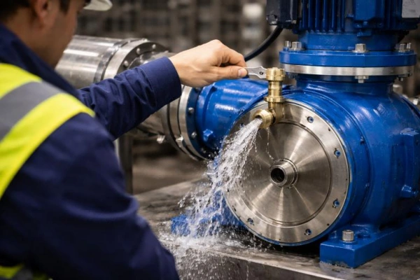
After completing the installation of the mechanical seal and leak inspection, you must also follow the correct operating procedures for priming the pump, venting, and starting the equipment, and continuously monitor the operating status of the mechanical seal.
Priming refers to the process of filling the pump body and associated suction system with liquid and expelling air prior to startup, thereby ensuring the pump is capable of properly conveying the medium.
Conventional centrifugal pumps rely on the rotation of the impeller to transfer mechanical energy to the liquid, thereby generating flow and pressure. If the pump cavity is filled with air, the impeller is generally unable to generate the required pressure as effectively as it would when conveying liquid.
Venting refers to the process of expelling residual air or gas from the pump housing, piping, or seal chamber through vent ports designed into the equipment.
If there is a significant amount of air inside the pump housing, it may interfere with the normal energy transfer between the impeller and the liquid, leading to unstable flow and pressure.
If gas is present in the seal chamber, it may also prevent the sealing faces from receiving adequate lubrication, affecting the formation and stability of the liquid film.
Different seal configurations have different requirements for auxiliary systems; it is incorrect to assume that all mechanical seals require an external water supply.
Pay special attention to the following systems:
If the mechanical seal uses an external flushing fluid, you must verify that the fluid source, pressure, flow rate, and piping connections meet design requirements.
If the seal is equipped with a quench system, you must verify the supply status of steam, nitrogen, or other specified media.
Also inspect the connections, valves, and discharge lines to ensure that the quench medium can enter the seal’s atmospheric side as required by the design.
For pressurized double-face mechanical seals, you must verify that the barrier fluid has fully filled the system and that the pressure, fluid level, and circulation status meet the manufacturer’s requirements.
The barrier fluid pressure must exceed the pressure of the process medium within the seal chamber to maintain the pressure differential specified in the design.
However, the specific pressure differential cannot be determined using a single universal value; it must be established based on the seal design and auxiliary system specifications.
After completing the pump priming, venting, and auxiliary system checks, you may start the pump in accordance with the equipment operating procedures.
Before startup, it is recommended that you double-check the following:
Just because the pump is running doesn’t mean the seal is stable. Pay close attention during startup and when operating conditions change, focusing on these five key indicators:
Leakage: Don’t expect zero visible leakage right from the start. Seals that rely on liquid-film lubrication naturally exhibit slight wetting; as long as there isn’t a steady stream or continuous dripping, it’s usually not a major issue.
Temperature: Ensure that the temperatures of the gland, seal chamber, and auxiliary piping do not rise continuously.
Abnormal temperature increases are most often caused by insufficient lubrication, inadequate flushing, dry grinding of the sealing faces, or vaporization of the medium.
Vibration: If vibration becomes significant, do not rush to replace the seal. In eight out of ten cases, the root cause lies in poor alignment, bearing failure, a bent shaft, or operating conditions that have deviated from normal—not the seal itself.
Pressure and Flow: Inlet and outlet pressures, as well as actual flow rates, must remain within normal ranges. Insufficient flow or abnormal pressure will degrade the cooling conditions in the seal chamber, causing the seal to fail quickly.
Auxiliary Systems: For external flushing, verify that pressure and flow are adequate. For double-face seals, closely monitor the pressure, level, and temperature of the isolation fluid. If the pressure drops or the level changes, immediately check for system leaks.
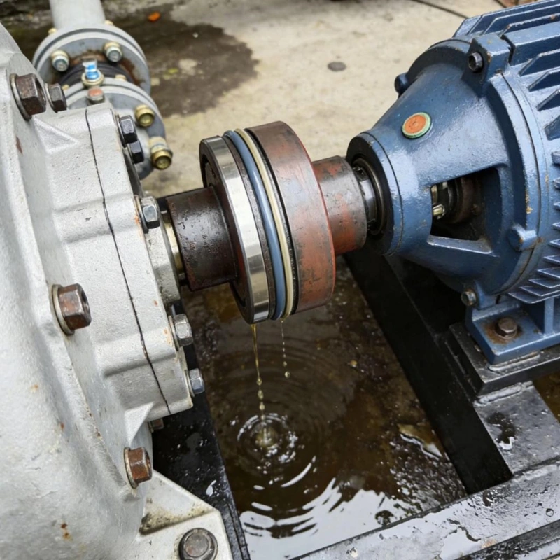
If a mechanical seal begins to leak immediately after installation, it indicates a problem with the installation process, component fit, the condition of the sealing faces, or the startup conditions. Unlike wear that occurs after a period of operation, leaks that occur early in the installation process typically require a priority check of assembly quality and auxiliary systems, rather than immediately concluding that the seal material or product is defective.
The first step in troubleshooting a leak is to pinpoint its exact location. Don’t rush to disassemble the entire seal assembly as soon as you see a leak, since the causes of failure vary significantly depending on the location:
Leaks around the gland: Check whether the gland packing is misaligned, whether the bolts are tightened to the correct torque, and whether the mating surfaces between the gland and the seal chamber are flat.
Leaks between the shaft sleeve and the seal: Focus on the dynamic O-ring to see if it is the wrong size, was twisted or scratched during installation, or if there are grooves on the surface of the shaft sleeve.
Leakage at the seal face: The face may have been bumped, contaminated with debris, not installed level, or dry-run due to a failure to form a stable lubricating film during operation.
Leakage at flushing line connections: Check whether the threads are properly tightened, whether a gasket is present, whether the fitting is fully seated, and whether the line pressure exceeds the specified limit.
Leaks in mechanical seals that occur before the pump starts require a different troubleshooting approach than those that occur after startup.
If the pump has not yet started and leakage occurs simply after filling the pump with liquid or establishing system pressure, the problem likely originates from the static seal area.
If there is no leakage while the pump is at a standstill, but leakage occurs immediately after startup, the problem may be related to dynamic sealing conditions.
For example, if a stable lubricating film has not formed between the rotating and stationary rings, abnormal friction may occur at the sealing faces; excessive shaft runout may also prevent the sealing faces from maintaining stable contact.
If it leaks right after installation, don’t rush to replace the part—it’s most likely a problem with the installation process. Focus on checking these four areas:
O-ring: It may have been nicked by threads or keyways during installation, twisted, or selected with the wrong size or material, causing it to fail immediately. Remove it and check for cuts, deformation, swelling, or extrusion marks, and while you’re at it, verify that the material grade and dimensions are correct.
Set Length: This dimension directly determines the compression of the spring or bellows. If installed too short, the spring is compressed too tightly, causing excessive end-face friction and rapid heating; if installed too long, the preload is insufficient, the end faces won’t seal tightly, and leaks will occur as soon as the unit is running.
Gland Bolts: If not tightened evenly in a diagonal pattern, the gland will tilt, causing the stationary ring to skew as well. This completely ruins end-face parallelism, and excessive localized stress will lead to leaks.
Sealing Face Scratches/Contamination: The sealing faces have extremely high precision. If they are bumped or scratched during installation, or if dust, metal shavings, or particulates enter, the lubricant film will be immediately destroyed, and leaks are inevitable once the system is running. Be sure to wipe the sealing faces clean before installation, and do not touch them directly with your hands.
Even if the mechanical seal itself is installed correctly, problems with the pump shaft or shaft sleeve can still cause leakage immediately after installation.
First, check the shaft surface and shaft sleeve for scratches, burrs, corrosion, or wear. Second, check for shaft runout and axial play. Additionally, check the alignment between the pump and the motor.
You cannot determine whether the shaft meets specifications by visual inspection alone. You should use appropriate measuring tools and compare the results with the allowable values specified by the pump and mechanical seal manufacturers.
During mechanical seal operation, an extremely thin liquid film is typically required between the rotating and stationary rings to reduce friction and dissipate heat.
If the liquid film cannot form stably, leakage may occur shortly after startup, even if the mechanical seal is installed correctly.
You should focus on checking the following aspects:
| Leakage Condition | Possible Cause | Inspection Focus |
|---|---|---|
| Leakage Before Pump Startup | Damaged O-ring, incorrect gasket installation, or abnormal face closure. | Check static seals and assembly positions. |
| Immediate Leakage After Startup | Poor face lubrication, damaged faces, or incorrect setting dimensions. | Inspect seal faces and installation dimensions. |
| Leakage Around the Gland | Damaged gasket or misaligned gland. | Check gland alignment and bolt tightening. |
| Leakage Near the Shaft Sleeve | Scratched, twisted, or incorrectly sized dynamic O-ring. | Inspect the shaft sleeve and secondary seals. |
| Leakage with Abnormal Heating | Dry running, insufficient fluid film, or excessive face friction. | Check the seal chamber and flushing system. |
| Leakage with Excessive Vibration | Shaft runout, axial movement, or poor coupling alignment. | Inspect the shaft system and equipment alignment. |
| Leakage at Flush Connections | Loose fittings or damaged threads and gaskets. | Inspect auxiliary piping connections. |
This is not recommended. Issues such as worn sealing faces and aged O-rings may affect sealing performance. Reuse should only be considered after a professional inspection has confirmed that the seal meets the required standards.
Yes, but you must verify that the other face is intact and matches the new face. It is generally recommended to replace paired, ground faces as a set.
It is recommended to replace them. Disassembly may cause the O-rings to become scratched or deformed, which can affect sealing performance after reinstallation.
Yes, depending on the pump’s design, seal type, and installation space. Some back-pull-out pumps allow for seal replacement without removing the motor.
Keep it in its original packaging and store it in a clean, dry, cool environment, away from sunlight, high temperatures, moisture, and compression.
This is not recommended. Oils and contaminants on your hands may contaminate the seal faces. Clean, lint-free gloves should be worn during installation.
Yes. Some seals are designed to be directional; you should confirm the shaft’s rotation direction and the seal’s intended orientation before ordering.
For installations involving high pressure, high temperature, hazardous media, complex double-face seals, and custom-made seals, it is recommended that the manufacturer or a qualified technician provide guidance.
Proper installation of mechanical seals not only effectively controls leakage but also reduces abnormal wear, equipment downtime, and subsequent maintenance costs. The installation process should not focus solely on the seal itself; it also requires a comprehensive inspection of the pump shaft and seal chamber condition, seal installation dimensions, face cleanliness, and the connections of auxiliary systems.
Sakowitz is committed to providing reliable mechanical seal solutions for pumps and rotating equipment, helping you reduce the risk of leakage and improve equipment operational stability and service life.
—— We Will Provide You With Professional OEM Solutions.
Whether you require pump bearings, pump valves, mechanical seals, or other custom-engineered components, we support production based on your drawings as well as rapid prototyping.
Please complete the form on the right and upload your technical drawings or specifications. Our engineering team will review your requirements within 24 hours and provide a detailed quotation, application recommendations, and delivery schedule.
Copyright © 2025 Sakowit, All rights reserved.
WhatsApp us