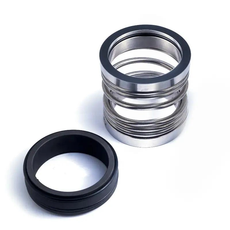

Do you know what a pusher mechanical seal is?Simply put, it is a mechanical seal where secondary seals, such as O-rings or wedges, can move along the shaft or sleeve during operation.As the seal faces wear, the spring pushes the sealing parts forward.This helps keep the rotating and stationary seal faces in contact.Pusher mechanical seals are commonly used in:
In this guide, I will help you understand pusher mechanical seals in depth.You will also learn about the common problems you may face in real applications.
A pusher mechanical seal is a mechanical seal in which secondary sealing parts move along the shaft or sleeve during operation.It uses O-rings, V-rings, or wedge-shaped seals as secondary sealing parts.These parts help prevent fluid from leaking between the shaft and the seal assembly.They also need to move as the seal faces gradually wear.Pusher mechanical seals usually have these features:
However, the secondary seals need to slide along the shaft or sleeve.If the surface has corrosion, scale, deposits, or wear grooves, the secondary seals may not move smoothly.This may stop the seal from compensating for wear and may increase the risk of leakage.So, when you use a pusher mechanical seal, you should not only check the seal faces.You should also check the shaft sleeve surface, fluid cleanliness, secondary seal materials, and operating temperature.
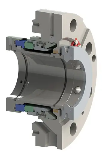
A pusher mechanical seal is a mechanical seal in which the secondary seal moves along the shaft or sleeve as the seal faces wear.The secondary sealing parts usually include:
Its most important feature is:The secondary seal must be able to slide along the shaft or sleeve surface.As the seal faces wear, the spring continues to push the seal assembly forward.At the same time, the secondary seal moves along the shaft or sleeve.This movement helps compensate for seal-face wear and keeps the rotating and stationary faces in contact.This is also the main difference between a pusher mechanical seal and a non-pusher mechanical seal.
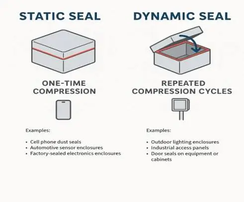
Do you know the difference between a dynamic secondary seal and a static secondary seal?In a mechanical seal, the secondary seal helps prevent fluid from leaking through areas other than the main seal faces.These areas may include the shaft, sleeve, rotating ring, or stationary ring.The main difference is not whether the part rotates.The key point is whether there is relative movement between the secondary seal and the surface it contacts.
| Comparison Item | Dynamic Secondary Seal | Static Secondary Seal |
|---|---|---|
| Meaning | Dynamic secondary seal | Static secondary seal |
| Relative Movement | Slides axially or moves relative to the contact surface | Usually has no relative movement |
| Common Types | O-ring, V-ring, wedge seal | O-ring, gasket |
| Main Function | Seals while allowing parts to move | Seals fixed connection points |
| Surface Requirement | Higher: the surface must allow smooth movement | Usually lower |
| Common Problems | Sticking, friction, wear, or deposits blocking movement | Aging, compression set, or material incompatibility |
For a pusher mechanical seal, the dynamic secondary seal is especially important.As the seal faces wear, the O-ring or other secondary seal needs to move along the shaft or sleeve.This allows the spring to keep pushing the seal faces together.A static secondary seal does not normally slide along the contact surface during operation.
Its main job is to seal a fixed connection point.You should also remember that static does not always mean the part does not rotate.Even if the secondary seal rotates with the shaft, it is still static if there is no relative movement against the nearby surface.
A pusher mechanical seal has several working parts. The main parts are the rotating face, stationary face, spring, and secondary seal.You can understand its structure through these main components:
| Component | Chinese | Main Function |
|---|---|---|
| Rotating Seal Face | 动环 | Rotates with the shaft and forms the main sealing surface with the stationary face |
| Stationary Seal Face | 静环 | Stays fixed in the seal chamber or gland and works with the rotating face to control leakage |
| Secondary Seal | 辅助密封 | Usually an O-ring, V-ring, or wedge seal that prevents leakage around the shaft or fitting areas |
| Spring | 弹簧 | Provides closing force to keep the two seal faces in contact |
| Shaft or Sleeve | 轴或轴套 | Supports the rotating seal parts and provides a sliding surface for the dynamic secondary seal |
| Gland | 压盖 | Holds the stationary face and installs the mechanical seal inside the seal chamber |
| Drive Component | 传动部件 | Transfers shaft rotation to the rotating seal assembly |
| Retainer / Metal Parts | 固定件 / 金属结构件 | Holds the spring, rotating face, and other seal parts in position |
The rotating face and stationary face form the main sealing faces.During operation, the rotating face turns with the shaft, while the stationary face stays still.The two carefully finished faces stay very close together to control fluid leakage.The secondary seal prevents leakage through areas outside the main seal faces.
In a pusher mechanical seal, this part is especially important.As the seal faces wear, the O-ring or another secondary seal needs to move along the shaft or sleeve.The spring keeps applying closing force to the seal faces.As the faces wear, the spring pushes the rotating seal assembly forward.
This helps you keep the rotating and stationary faces in contact.With a pusher mechanical seal, you should also pay special attention to the shaft sleeve surface.If the sleeve has corrosion, scale, scratches, or deposits, the dynamic secondary seal may not move smoothly.This can reduce wear compensation and affect the overall sealing performance.
In a pusher mechanical seal, the rotating seal face and stationary seal face form the main sealing surfaces.The rotating face is usually connected to the shaft or sleeve and rotates with the shaft.The stationary face is usually installed in the gland or seal chamber and stays still during operation.
During operation, the rotating face moves at high speed against the stationary face.The two carefully finished surfaces stay very close together to control fluid leakage.If the two faces press together too tightly, friction and temperature may increase.The fluid film may also become too thin.If the gap between the faces is too large, friction may decrease, but leakage may increase.
So, you need enough contact between the rotating and stationary faces without creating excessive face loading.You should also pay attention to the seal-face materials and surface condition.If the faces have scratches, cracks, deformation, particle contamination, or unusual wear, the fluid film and sealing contact may be affected.This can increase the risk of leakage.
In a pusher mechanical seal, the spring, dynamic O-ring, and shaft sleeve play important roles.The spring provides the closing force that keeps the rotating and stationary seal faces in contact.As the seal faces wear, the spring keeps pushing the seal assembly forward to make up for the wear.If the spring becomes corroded, broken, weak, or blocked by deposits, the seal faces may not get enough closing force.
This can increase the risk of leakage.The dynamic O-ring provides secondary sealing and also needs to slide along the shaft or sleeve.This is one of the key features of a pusher mechanical seal.As the seal faces wear, the dynamic O-ring must move smoothly so the spring can keep pushing the rotating seal assembly.If the O-ring swells, hardens, wears, sticks, or is not compatible with the fluid, it may not move properly.
The shaft sleeve provides the sliding surface for the dynamic O-ring and also protects the shaft from wear and corrosion.So, you should carefully check the shaft sleeve for:
If the sleeve surface is too rough or badly damaged, the dynamic O-ring may stick or wear.This can reduce the seal’s ability to compensate for wear and may cause leakage or early failure.So, when you inspect a pusher mechanical seal, you should not look only at the seal faces.You should also check whether the spring moves freely, the O-ring slides smoothly, and the shaft sleeve surface is suitable for dynamic sealing.

In a pusher mechanical seal, the drive mechanism transfers rotation from the shaft or sleeve to the rotating seal assembly.Common drive parts include:
These parts do not usually provide sealing directly.However, they help the rotating seal face rotate smoothly and at the same speed as the shaft.If the drive mechanism becomes loose, worn, or deformed, it may cause:
The hardware mainly holds the springs, seal rings, and other mechanical seal parts in the correct position.You should carefully check these parts for:
So, when you inspect a pusher mechanical seal, you should not only check the seal faces, springs, and O-rings.You should also make sure the drive mechanism transfers torque reliably and all hardware is free from looseness, wear, or damage.
Do you know how a pusher mechanical seal works?The key is using spring force, fluid pressure, and a movable secondary seal to keep the rotating and stationary faces in proper contact.When the equipment starts, the shaft drives the rotating seal face while the stationary seal face stays still.The two carefully finished seal faces stay very close together.
A very thin fluid film usually forms between them.This fluid film helps you reduce friction, remove some heat, and control fluid leakage.As the seal faces gradually wear, the seal assembly needs to move forward.The spring pushes the rotating seal assembly forward.At the same time, the dynamic secondary seal, such as an O-ring, slides along the shaft or sleeve.
This movement helps compensate for seal-face wear and keeps the rotating and stationary faces in contact.If the dynamic O-ring is blocked by corrosion, scale, or deposits, it may not slide smoothly.Even if the spring still provides force, the seal may not properly compensate for face wear.
This can increase the risk of leakage.So, when you inspect a pusher mechanical seal, you should check the seal faces, spring, dynamic O-ring, and shaft sleeve surface.You should not look only at the rotating and stationary faces.
In a pusher mechanical seal, the rotating and stationary faces stay in contact mainly because of two forces: spring force and hydraulic closing force.Spring force provides the basic closing force during startup, shutdown, or when system pressure is low.As the seal faces wear, the spring keeps pushing the rotating seal assembly forward.This helps compensate for seal-face wear.Hydraulic closing force comes from fluid pressure.
When fluid pressure acts on the seal’s effective hydraulic area, it creates force that pushes the rotating and stationary faces together.As system pressure increases, this closing force usually becomes stronger.Proper closing force can help you:
However, more closing force is not always better.If the closing force becomes too high, it may cause:
So, when you select or inspect a pusher mechanical seal, you should consider spring load, fluid pressure, effective hydraulic area, and face loading together.
In a pusher mechanical seal, the seal assembly needs to keep moving axially as the rotating and stationary faces wear.This movement helps you keep the two seal faces in contact.The compensation process mainly depends on spring force.As the seal faces wear, the spring keeps pushing the rotating seal assembly forward.At the same time, the dynamic secondary seal must slide along the shaft or sleeve surface.
This axial movement is an important feature of a pusher mechanical seal.If the dynamic O-ring or another secondary seal cannot move smoothly, the seal may not properly compensate for face wear.Common causes include:
If the secondary seal sticks, the rotating seal assembly may not move forward even if the spring still provides force.This may reduce face contact force and increase the risk of leakage or early seal failure.So, when you inspect a pusher mechanical seal, you should make sure the dynamic secondary seal moves freely.You should also check that the shaft sleeve surface is smooth, clean, and free from obvious damage.
In a pusher mechanical seal, the dynamic O-ring provides secondary sealing and also slides along the shaft or sleeve as the seal moves axially.As the seal faces wear, the spring keeps pushing the rotating seal assembly forward.At the same time, the O-ring moves axially with the seal assembly.While sliding, the O-ring has two main jobs:
So, friction between the O-ring and shaft sleeve should not be too high.If the sleeve has corrosion, scale, scratches, wear grooves, or solid deposits, the O-ring may become stuck.If the O-ring swells, hardens, ages, or is not compatible with the fluid, sliding resistance may also increase.If the O-ring cannot move smoothly, the rotating seal assembly may not compensate for face wear, even if the spring still provides force.
This may reduce face contact force and increase the risk of leakage or early seal failure.So, when you inspect a pusher mechanical seal, you should make sure the O-ring can slide freely.You should also check that the shaft or sleeve surface is smooth, clean, and free from obvious damage.
Pusher mechanical seals do not have only one design.The main differences usually come from the secondary seal type, number of springs, and spring arrangement.You can understand the common designs from the table below:
| Design Type | Chinese | Main Feature | Typical Consideration |
|---|---|---|---|
| O-Ring Pusher Seal | O 形圈推压式密封 | Uses a dynamic O-ring that slides along the shaft or sleeve | Common design, but you should watch for O-ring sticking and material compatibility |
| Wedge Pusher Seal | 楔形圈推压式密封 | Uses a wedge-shaped secondary seal for sealing and axial movement | More sensitive to installation and contact surface condition |
| V-Ring Pusher Seal | V 形圈推压式密封 | Uses a V-ring secondary seal that allows axial movement | You should consider wear, aging, and sliding resistance |
| Single-Spring Seal | 单弹簧机械密封 | Uses one larger spring to provide closing force | Simple design, but contamination may affect spring movement |
| Multiple-Spring Seal | 多弹簧机械密封 | Uses several small springs placed evenly around the seal | Usually gives more even force, but small springs are more sensitive to particles and deposits |
| Wave-Spring Seal | 波形弹簧机械密封 | Uses a wave spring to provide axial closing force | Requires less axial space, but spring load must be designed correctly |
A single-spring design usually uses one large coil spring to push the seal assembly.Its main advantage is a simple structure with fewer parts.However, deposits, crystals, or particles in the fluid may contaminate the spring.This can affect normal spring compression and movement.
A multiple-spring design uses several smaller springs placed evenly around the shaft.This design can apply closing force more evenly across the seal faces.However, you should remember that small springs are more easily blocked by particles, crystals, or deposits.
A wave spring uses a wave-shaped metal structure to create axial spring force.It can provide the required closing force in a smaller axial space.This makes it useful when installation space is limited.However, I want to remind you that spring design alone cannot determine whether a seal is suitable for your equipment.When selecting a seal, you should also consider pressure, temperature, speed, fluid cleanliness, corrosion, crystallization risk, and installation space.
In pusher mechanical seals, two common spring designs are the Single-Spring Design and the Multi-Spring Design.Both designs provide axial closing force to keep the rotating and stationary faces in contact.They also keep pushing the seal assembly forward as the seal faces wear.
| Comparison Item | Single-Spring Design | Multi-Spring Design |
|---|---|---|
| Number of Springs | Usually uses one large coil spring | Uses several small springs |
| Closing Force | Provided by one spring | Shared by several springs |
| Structure | Relatively simple | More complex |
| Sensitivity to Particles and Deposits | Usually lower | Small springs are more easily affected by particles or crystals |
| Load Distribution | Depends on the overall seal design | Usually provides more even axial loading |
| Maintenance | Usually easier | You need to check several small springs |
| Common Concerns | Corrosion, fatigue, or blockage | Blockage, corrosion, or uneven spring force |
A single-spring design usually uses one large coil spring to push the seal assembly.This design is relatively simple and has fewer parts.It is also usually easier for you to inspect and maintain.For fluids with some particles, deposits, or crystallization, one large spring is usually less likely to become fully blocked than many small springs.
A multi-spring design uses several small springs placed evenly around the seal.This helps distribute the closing force more evenly across the seal faces.It can also help you maintain more even face loading and stable contact.However, you should know that small springs are more sensitive to particles, crystals, deposits, and corrosion.If some springs become stuck, the face load may become uneven.This can increase the risk of unusual wear or leakage.
You should know that in a pusher mechanical seal, wave-spring, wedge, and O-ring designs are not exactly the same type of design.A wave spring mainly controls how the mechanical seal provides axial closing force.A wedge and an O-ring mainly work as dynamic secondary seals.
A wave-spring design uses a wave-shaped metal spring to create axial closing force.Compared with a normal coil spring, it can usually provide the required spring force in a shorter axial space.This makes it useful when you have limited installation space.
A wedge design uses a wedge-shaped secondary seal against the shaft or sleeve.In a pusher seal, the wedge must maintain sealing while allowing the seal assembly to move axially.Its shape helps create sealing pressure.However, you should pay special attention to installation direction, compression, and shaft sleeve condition.
An O-ring design is a very common secondary sealing design in pusher mechanical seals.The O-ring sits between the seal assembly and the shaft or sleeve.It prevents fluid leakage and also slides axially as the seal faces wear.The design is simple and widely used, but you should carefully check:
If the O-ring becomes stuck, the spring may still provide force, but the seal assembly may not move forward correctly.This can stop the seal from properly compensating for face wear.So, when you select these designs, you should consider installation space, spring load, fluid properties, temperature, shaft sleeve condition, and secondary-seal material compatibility.
Pusher mechanical seals can be designed as either balanced or unbalanced.Both types use a dynamic secondary seal that moves along the shaft or sleeve.The main difference is how the seal faces are loaded.A balanced pusher seal reduces the effective area exposed to fluid pressure through its design.This lowers face loading and can help you reduce:
So, if your equipment operates under higher pressure, higher speed, or with low-lubricity fluids, a balanced pusher seal is usually worth considering.An unbalanced pusher seal usually has a simpler design.At the same pressure, it often has a higher closing force on the seal faces.This can help you maintain tighter face contact under lower-pressure and stable operating conditions.This design usually offers:
However, as pressure increases, face loading in an unbalanced pusher seal may also rise significantly.This can lead to more friction, heat, and wear.
Do you know the main advantages of pusher mechanical seals?Their main advantages include:
However, these advantages depend on one important condition:The dynamic secondary seal must be able to slide smoothly.If the shaft sleeve has corrosion, scale, deposits, or wear grooves, the O-ring may stick.This can prevent proper wear compensation.So, the advantages of a pusher mechanical seal do not depend only on its design.You should also consider the shaft sleeve condition, fluid cleanliness, and whether the secondary seal material is suitable.
Pusher mechanical seals are often compact, cost-effective, and widely available, so they are commonly used in many pumps and industrial machines.First, their structure is usually compact.Many pusher seals use O-rings, springs, and simple metal parts, so they do not need very complex internal designs.This can help you:
Second, pusher mechanical seals often offer a cost advantage.Compared with more complex seal designs, their parts and machining requirements are usually easier to control.This often means a lower initial purchase cost.For standard water pumps, centrifugal pumps, and general industrial equipment, this design can be a cost-effective choice.Pusher mechanical seals are also widely available in the market.
Many seal manufacturers offer pusher seals in different sizes, materials, spring designs, and secondary seal types.This means you can usually find:
However, wide availability and lower cost do not mean that all pusher seals are directly interchangeable.You still need to check shaft size, installation dimensions, pressure, temperature, speed, fluid, seal-face materials, and O-ring materials for your equipment.
Another advantage of pusher mechanical seals is their flexible material selection and suitability for many common industrial applications.You can choose different seal-face and secondary-seal materials based on the fluid, temperature, pressure, and corrosion conditions.Common seal-face materials include:
Common secondary-seal materials include:
This flexibility helps you handle different types of water, oil, mild chemicals, and general industrial fluids.For many general-duty applications, pusher mechanical seals are usually easy to match.Common applications include:
However, you should not assume that a material is suitable for your fluid just because it is commonly used.You still need to check chemical compatibility, temperature range, pressure, speed, fluid cleanliness, and whether particles or crystals are present.
Do you know the main limitation of a pusher mechanical seal?The key issue is that the dynamic secondary seal must slide along the shaft or sleeve.If this sliding movement is not smooth, the seal may not properly compensate for seal-face wear.The most common problem is hang-up.If the O-ring, V-ring, or wedge is blocked by corrosion, scale, deposits, crystals, or a rough surface, the seal assembly may stop moving.
This can happen even if the spring still provides force.It may cause:
Common failure modes also include:
| Failure Mode | Common Cause | Possible Result |
|---|---|---|
| Secondary Seal Hang-Up | Corrosion, scale, deposits, crystallization | Seal cannot compensate for face wear |
| O-Ring Swelling or Hardening | Poor material compatibility or high temperature | Higher sliding resistance or leakage |
| Shaft Sleeve Wear | Long-term sliding, rough surface, contamination | O-ring damage and unstable movement |
| Spring Corrosion or Fatigue | Corrosive fluid, long service, contamination | Reduced closing force |
| Seal-Face Wear | High face load, poor lubrication, particles | More leakage and shorter seal life |
| Dry Running | Loss of liquid film or fluid supply | Rapid heat buildup and face damage |
| Particle Damage | Solids entering the seal faces | Scratches, unstable film, leakage |
| Misalignment or Vibration | Shaft, bearing, or coupling problems | Uneven face loading and abnormal wear |
So, when you inspect a pusher mechanical seal, you should not only check where the leakage comes from.You should also check whether the dynamic O-ring moves freely, the sleeve surface is smooth, and the spring works properly.You should also check for seal-face wear, deposits, and solid particles in the fluid.
In a pusher mechanical seal, the dynamic O-ring must slide along the shaft or sleeve.So, the surface condition under and around the O-ring is very important.If coking occurs, hard deposits formed at high temperature may build up around the O-ring.These deposits increase sliding resistance.In serious cases, they can make the O-ring stick and stop the seal from compensating for face wear.Crystallization can cause similar problems.
When crystals form because of temperature changes, concentration changes, or fluid evaporation, they may enter the space between the O-ring and sleeve.This may cause:
Corrosion can also damage the shaft or sleeve surface.If pitting, rough areas, or corrosion grooves form under the O-ring, the O-ring may not slide smoothly.A rough surface can also damage the O-ring and increase leakage at the secondary sealing area.
So, when you inspect a pusher mechanical seal, you should carefully check the area under the O-ring and the sliding surface.You should look for coking, crystallization, corrosion, or other deposits.If the fluid easily causes coking, crystallization, or severe corrosion, you should also evaluate material selection, temperature control, flushing, and whether a pusher design is suitable.
In a pusher mechanical seal, the elastomer, such as an O-ring, can wear if the sleeve is rough or particles are present.Repeated O-ring sliding can also cause:
Fretting usually happens when two contact surfaces have small but repeated relative movement.In a mechanical seal, vibration, shaft runout, or slight axial movement can create this small movement between the O-ring and sleeve.Over time, wear marks or grooves may form on the shaft sleeve.This can damage the O-ring and make it harder for the O-ring to slide smoothly.
As a result, you may face higher risks of hang-up and leakage.Dry running is another serious problem.If there is not enough liquid between the seal faces, a stable fluid film cannot form.This causes more direct contact between the rotating and stationary faces and quickly creates frictional heat.Dry running may cause:
So, when you inspect a pusher mechanical seal, you should check O-ring wear, fretting marks on the sleeve, and any signs of dry running.If these problems exist, replacing only the seal faces is usually not enough.You should also check the shaft sleeve surface, vibration, fluid supply, and O-ring material.
In a pusher mechanical seal, the surface condition of the shaft or sleeve directly affects whether the dynamic O-ring can slide smoothly.If the sleeve surface is too rough, the O-ring may experience more friction and wear as it moves.Common problems include:
If the sleeve has scratches, corrosion, burrs, or deposits, these problems may become more serious.Besides surface condition, you should also pay attention to shaft deflection.If shaft deflection becomes too large, the rotating face may not stay properly aligned with the stationary face.This may cause:
Shaft deflection may also be related to worn bearings, an overly long shaft, excessive load, or poor equipment alignment.So, when you inspect a pusher mechanical seal, you should not check only the seal itself.You should also check whether the shaft or sleeve is smooth and undamaged, and whether there is clear deflection, runout, or vibration during operation.
Pusher mechanical seals are used in many industries.They are especially suitable when the fluid is relatively clean, the shaft sleeve is in good condition, and the dynamic secondary seal can move smoothly.You can understand their typical applications from the table below:
| Industry | Typical Equipment | Common Fluids | Why Pusher Seals Are Used |
|---|---|---|---|
| Water Treatment | Water pumps, circulation pumps | Clean water, treated water | Simple structure, lower cost, and easy maintenance |
| HVAC | Chilled-water pumps, cooling-water pumps | Water, glycol mixtures | Suitable for common temperature and pressure ranges, with standard sizes widely available |
| Chemical Processing | Process pumps, transfer pumps | Mild chemicals, solvents | You can adapt them to different fluids by changing face and O-ring materials |
| Oil & Gas | Process pumps, transfer pumps | Oils, hydrocarbons | You can choose balanced or unbalanced designs based on pressure |
| Petrochemical | Centrifugal pumps, process pumps | Hydrocarbons, process liquids | Suitable for many standard pumps, but you should check volatility and material compatibility |
| Food & Beverage | Process pumps, utility pumps | Water, cleaning fluids, some food liquids | Compact design, but you need suitable sanitary materials and elastomers |
| Pharmaceutical | Utility and process pumps | Purified water, process fluids | Suitable for some clean services, but material and cleaning requirements are stricter |
| Pulp & Paper | Process and water pumps | Water, light process fluids | Can be used when the fluid is relatively clean |
| Power Generation | Cooling-water and utility pumps | Water, condensate | Commonly used in general utility pumps and water systems |
| General Manufacturing | Coolant pumps, circulation pumps | Water, oils, coolants | Many sizes are available, with controlled cost and easy replacement |
In water treatment and HVAC, pusher mechanical seals are common because the fluids are usually relatively clean and operating conditions are stable.In chemical, oil and gas, and petrochemical applications, you should pay more attention to fluid corrosion, volatility, lubricity, and temperature.I want to especially remind you that you should not choose a pusher mechanical seal based only on the industry name.You should also consider fluid properties, pressure, temperature, speed, particle content, material compatibility, and shaft sleeve condition.
Pusher mechanical seals are also commonly used in water supply pumps, circulation pumps, drainage pumps, and some wastewater pumps.For clean water pumps, the fluid is usually relatively clean.This allows the dynamic O-ring to move more smoothly along the shaft or sleeve.As a result, pusher mechanical seals can usually operate more steadily.Common applications include:
In wastewater pumps, operating conditions are usually more difficult.Wastewater may contain:
These materials may enter the sealing area and affect the dynamic O-ring, spring, and seal faces.If particles or deposits enter the O-ring sliding area, they may cause hang-up.This can stop the seal from properly compensating for face wear.It may also increase the risk of leakage or early seal failure.So, if you use a pusher mechanical seal in a wastewater pump, you should carefully check:
Pusher mechanical seals are also commonly used in oil transfer pumps, process pumps, circulation pumps, and some petrochemical equipment.For oils with good lubricating ability, the dynamic O-ring can usually move more smoothly along the shaft or sleeve.This helps the seal assembly compensate for face wear and maintain stable contact.Common applications include:
However, petrochemical fluids usually create more complex operating conditions than ordinary water service.You should pay special attention to:
Pusher mechanical seals are also commonly used in pulp and paper equipment, process pumps, and various general industrial rotating machines.In these applications, fluids usually include water, diluted liquids, lubricants, and some low-concentration process fluids.If the fluid is relatively clean, the dynamic O-ring can usually move smoothly along the shaft or sleeve.
This helps the seal assembly compensate for face wear and maintain reliable operation.Common applications include:
In the pulp and paper industry, you should pay special attention to fibers, particles, and chemical additives in the fluid.These materials may enter the sealing area and affect:
If fibers or solid particles enter the O-ring sliding area, they may cause hang-up.This can reduce the seal’s ability to compensate for wear and increase the risk of leakage.For general industrial pumps, pusher mechanical seals usually offer simple structures, many available sizes, and easy replacement.However, you still need to choose suitable:
So, in pulp, paper, and general industrial applications, you should not choose a pusher mechanical seal based only on the equipment type.You should also consider fluid cleanliness, particle content, temperature, pressure, speed, and shaft sleeve condition to decide whether it is suitable.
Pusher mechanical seals can be used in many industrial machines, but they are not suitable for every operating condition.You need to select them based on fluid properties, pressure, temperature, and seal materials.In general, pusher mechanical seals work best with clean or slightly contaminated fluids under low to medium pressure and controlled temperatures.The table below helps you understand their common operating range.
| Selection Factor | Suitable Condition | Common Examples | Key Considerations |
|---|---|---|---|
| Fluid Type | Clean or relatively clean fluids | Clean water, treated water, cooling water, oils, lubricants, mild chemicals, general process fluids | You should check chemical compatibility between the fluid and O-ring/seal-face materials |
| Fluid Cleanliness | Low solid content and fewer deposits | Water systems, utility pumps, general process applications | Particles, fibers, crystals, and deposits may cause O-ring hang-up |
| Pressure Range | Low to medium pressure applications | Water pumps, circulation pumps, general industrial pumps | Higher pressure may increase face loading and may require balanced designs |
| High Pressure Service | Possible with proper design selection | Oil transfer pumps, petrochemical pumps | You should evaluate balanced design, face load, cooling, and flushing conditions |
| Temperature Range | Moderate and controlled temperatures | Water systems, general process fluids | You need suitable O-ring, seal-face, and spring materials |
| High Temperature Service | Requires careful material selection | Hot process fluids, chemical equipment | High temperature may cause O-ring hardening, material aging, and fluid vaporization |
| Lubricity | Good or moderate lubricity fluids | Oils, lubricants, many process fluids | Poor lubrication may increase friction, heat, and seal-face wear |
| Particle Content | Low particle content | Clean water, filtered process fluids | Solid particles may damage seal faces and block dynamic O-rings |
| Corrosion Risk | Mild corrosion conditions | Mild chemicals, treated fluids | You need compatible seal-face and elastomer materials |
| Shaft/Sleeve Condition | Smooth and clean surfaces | Standard rotating equipment | Rough surfaces, corrosion, grooves, or deposits may prevent O-ring movement |
Pusher mechanical seals are usually suitable for clean or slightly contaminated fluids, low to medium pressure, and controlled temperature applications.They offer good flexibility in water pumps, circulation pumps, process pumps, and general industrial equipment.However, you should not decide suitability only based on the fluid name or equipment type.
A more reliable method is to evaluate:Fluid properties, pressure, temperature, speed, particle content, corrosion risk, and shaft sleeve condition.Only when the dynamic O-ring can move properly and the seal faces remain stable can you get the full benefits of a pusher mechanical seal.
Do you know which clean or slightly contaminated industrial fluids are usually suitable for pusher mechanical seals?When the fluid is relatively clean, the O-ring can usually move smoothly.This allows the seal assembly to compensate for wear through normal axial movement.Common suitable fluids include:
However, pusher mechanical seals can also be used for some moderately contaminated fluids.Examples include:
When you choose a pusher mechanical seal for clean or moderately contaminated fluids, you should carefully check:
| Selection Factor | What You Should Check |
|---|---|
| Fluid Cleanliness | Particle content and deposit risk |
| Shaft Sleeve Condition | Smooth surface without scratches or corrosion |
| O-Ring Material | Compatibility with the fluid |
| Seal Face Material | Wear resistance and chemical resistance |
| Flushing Condition | Whether additional flushing is needed |
Therefore, pusher mechanical seals are usually suitable for clean and slightly contaminated fluids.However, for fluids with high solid content, crystallization, coking, or heavy deposits, you should reevaluate the hang-up risk and whether this seal design is suitable.
In a pusher mechanical seal, the elastomer is an important part that affects sealing reliability.It not only needs good sealing performance but also requires good elasticity, temperature resistance, and material stability.You need to select the right elastomer based on the fluid and operating temperature.Common elastomer materials include:
| Elastomer Material | Common Application | Key Considerations |
|---|---|---|
| NBR (Nitrile Rubber) | Oils, lubricants, general water service | Lower cost, but performance is limited at high temperatures and with some chemicals |
| EPDM | Water, steam, glycol-based fluids | Good water resistance, but not suitable for most oils |
| FKM (Viton®) | Oils, hydrocarbons, chemical fluids | Good high-temperature and chemical resistance |
| PTFE | Strong chemicals, high-temperature applications | Excellent chemical stability, but lower elasticity and dynamic movement ability |
Temperature directly affects elastomer performance.When the temperature is too low, you may experience:
When the temperature is too high, you may see:
Therefore, when you select an elastomer for a pusher mechanical seal, you need to evaluate fluid compatibility, temperature, pressure, sliding conditions, and shaft sleeve condition together.A material that works well in one application may not perform well in another if the operating conditions are different.
The main difference between Pusher Mechanical Seals and Non-Pusher Mechanical Seals is whether the secondary seal moves axially as the seal faces wear.Both designs keep the rotating and stationary seal faces in contact, but they compensate for wear in different ways.
| Comparison Factor | Pusher Mechanical Seal | Non-Pusher Mechanical Seal |
|---|---|---|
| Chinese Name | Pusher mechanical seal | Non-pusher mechanical seal |
| Secondary Seal Movement | The dynamic secondary seal moves along the shaft or sleeve | The secondary seal usually stays fixed and does not slide with the assembly |
| Wear Compensation | The spring pushes the seal assembly, and the dynamic O-ring moves to compensate for wear | Wear is usually compensated by the flexible element design without secondary seal sliding |
| Common Secondary Seal | O-ring, V-ring, Wedge | Bellows and static sealing structures |
| Main Feature | Simple structure and direct wear compensation | Avoids dynamic O-ring sliding problems |
| Shaft Sleeve Requirement | Requires good shaft sleeve surface condition | Less dependent on sliding surface condition |
| Common Failure Risk | O-ring hang-up, wear, and deposits blocking movement | Bellows fatigue, damage, or corrosion |
| Maintenance Consideration | You need to check O-ring movement and shaft sleeve condition | You need to check bellows condition and material performance |
| Typical Applications | Water pumps, industrial pumps, general equipment | High-temperature, corrosive, or difficult sealing applications |
Pusher mechanical seals use dynamic secondary seal movement to compensate for wear.This design is simple and widely used, but you need good shaft sleeve conditions and relatively clean fluids.Non-pusher mechanical seals avoid dynamic secondary seal sliding.
This can help you reduce hang-up risks in some special operating conditions.When you choose between these two designs, you need to consider fluid properties, pressure, temperature, speed, shaft sleeve condition, maintenance requirements, and material compatibility.
In mechanical seals, Sliding O-ring and Flexible Bellows are both types of secondary sealing structures.Their main difference is:A sliding O-ring moves axially along the shaft or sleeve, while a flexible bellows compensates for wear through elastic movement without sliding.
| Comparison Factor | Sliding O-Ring | Flexible Bellows |
|---|---|---|
| Chinese Name | Sliding O-ring | Flexible bellows |
| Movement Method | The O-ring slides along the shaft or sleeve | The bellows moves through elastic deformation |
| Wear Compensation | The spring pushes the seal assembly, and the O-ring moves as the seal faces wear | The bellows expands and contracts to compensate for wear |
| Contact with Shaft | Requires sliding contact with the shaft or sleeve | Does not have sliding contact with the shaft |
| Surface Requirement | Requires a smooth and clean sliding surface | Less dependent on shaft surface condition |
| Common Materials | NBR, EPDM, FKM, PTFE | Rubber bellows, metal bellows |
| Main Advantage | Simple structure, common design, and easy replacement | Avoids O-ring sticking and sliding wear |
| Common Risk | O-ring hang-up, swelling, wear, and deposits blocking movement | Bellows fatigue, cracking, corrosion, and material damage |
| Particle Sensitivity | More sensitive because particles can affect sliding movement | Usually less affected by shaft surface deposits |
| Typical Applications | Water pumps, general industrial pumps, standard equipment | High-temperature, corrosive, or difficult sealing applications |
When you select between these two designs, you need to consider fluid properties, temperature, pressure, particle content, shaft sleeve condition, maintenance requirements, and material compatibility.
When you choose between Sliding O-ring and Flexible Bellows, you should not only compare the initial cost.You also need to consider temperature, fluid contamination, maintenance frequency, and long-term operating reliability.Both designs have their own advantages, and the right choice depends on your operating conditions.
| Comparison Factor | Sliding O-Ring | Flexible Bellows |
|---|---|---|
| Initial Cost | Usually lower cost because of its simple structure and common design | Usually higher cost because it has more complex components |
| Maintenance Cost | You may need to pay more attention to O-ring movement and sleeve condition | May reduce sliding-related maintenance, but you need to inspect the bellows |
| Temperature Capability | Strongly depends on O-ring material temperature limits | Often suitable for higher-temperature applications with proper material selection |
| Fouling Resistance | More sensitive to deposits, crystals, and particles | Less affected by shaft surface deposits because there is no sliding O-ring |
| Particle Sensitivity | Particles may block O-ring movement and cause hang-up | Particles mainly affect seal faces or bellows condition |
| Shaft Surface Requirement | Requires a smooth and clean shaft or sleeve surface | Less dependent on the shaft sliding surface condition |
| Common Risk | O-ring swelling, hardening, wear, and hang-up | Bellows fatigue, cracking, corrosion, or material damage |
When you choose between these two designs, you should evaluate:Cost, temperature, fluid cleanliness, deposit risk, maintenance requirements, and material compatibility.
When you choose between Sliding O-ring and Flexible Bellows, material compatibility is a very important factor.You should not only consider the seal design itself.You also need to check whether the seal materials can work with your fluid, temperature, and operating environment for a long time.If you choose unsuitable materials, you may experience:
| Material Factor | Sliding O-Ring | Flexible Bellows |
|---|---|---|
| Common Elastomer Materials | NBR, EPDM, FKM, PTFE | Rubber bellows, metal bellows |
| Main Material Concern | The O-ring must maintain sealing performance and smooth sliding | The bellows must maintain flexibility and strength |
| Fluid Compatibility | You need to check whether the fluid affects O-ring performance | You need to check whether the fluid damages the bellows material |
| Temperature Effect | High temperature may cause O-ring aging, swelling, or hardening | High temperature may reduce bellows strength and fatigue life |
| Chemical Resistance | Mainly depends on the elastomer type | Depends on bellows material and surface protection |
| Dynamic Movement | The O-ring must maintain low friction during sliding | The bellows must repeatedly flex without damage |
In a Sliding O-ring mechanical seal, the O-ring not only provides secondary sealing but also moves along the shaft or sleeve.Therefore, when you choose an O-ring material, you should not only consider sealing performance.You also need to consider:
| Fluid Type | Recommended O-Ring Materials | Key Considerations |
|---|---|---|
| Water and Clean Water | EPDM, NBR | EPDM has good water resistance; NBR is commonly used for general applications |
| Oil and Lubricants | NBR, FKM | You need good oil resistance and stable long-term performance |
| Hydrocarbons | FKM, PTFE | You should consider chemical resistance and temperature conditions |
| Steam and Hot Water | EPDM, FKM, PTFE | High temperature may reduce elastomer service life |
| Mild Chemicals | FKM, EPDM, PTFE | You need to carefully check chemical compatibility |
| Strong Chemicals | PTFE, special materials | Standard elastomers may swell or degrade |
| Food and Pharmaceutical Fluids | FDA-compliant elastomers, PTFE | You need to consider hygiene requirements and regulations |
If the O-ring material is not compatible with the fluid, you may experience:
In a mechanical seal, the material selection of Seal Faces and Metal Parts directly affects sealing performance, service life, and operating stability.You should not only consider material hardness.You also need to consider:
Common seal-face materials include:
| Seal-Face Material | Common Applications | Key Considerations |
|---|---|---|
| Carbon | Water pumps, general industrial fluids | Good self-lubrication and low friction, but wear resistance may be limited in some conditions |
| Silicon Carbide | Chemicals, high-wear applications | Excellent hardness, wear resistance, and corrosion resistance |
| Tungsten Carbide | Heavy-duty equipment, abrasive fluids | High wear resistance and suitable for harsh operating conditions |
| Ceramic | Water and general applications | Good corrosion resistance, but more sensitive to impact |
Common metal parts in mechanical seals include:
When you select materials for a pusher mechanical seal, you should not choose seal-face and metal materials only based on the equipment type.You need to select the right combination based on fluid properties, operating conditions, and material compatibility.The correct material combination can help you reduce leakage risk, improve seal life, and maintain stable operation.
When you install and maintain a Pusher Mechanical Seal, proper operation is very important.Because a pusher mechanical seal uses a Dynamic Secondary Seal that moves along the shaft or sleeve to compensate for face wear, you need to check not only the seal faces but also the sleeve, O-ring, spring, and operating conditions.A complete inspection process can help you reduce leakage risks and extend seal life.
Proper installation and maintenance can not only reduce leakage but also help you avoid O-ring hang-up, dry running, abnormal wear, and early seal failure.
When you install and maintain a Pusher Mechanical Seal, shaft finish, runout, and alignment are important factors that affect seal performance.
| Inspection Factor | What You Should Check | Possible Problems | Impact on Pusher Mechanical Seal |
|---|---|---|---|
| Shaft / Sleeve Finish | You should check if the surface is smooth, clean, and free from scratches, corrosion, grooves, and deposits | Rough surfaces, corrosion, wear marks, or contamination | Increases O-ring friction, makes movement difficult, and increases hang-up risk |
| Dynamic O-Ring Sliding Surface | You should confirm that the O-ring can move smoothly along the shaft or sleeve | Surface damage, deposits, or poor surface condition | Prevents wear compensation and may increase leakage risk |
| Shaft Runout | You should check whether the shaft rotates within an acceptable movement range | Bent shaft, bearing wear, machining errors, or excessive load | Causes uneven seal-face contact, vibration, and abnormal wear |
| Seal-Face Contact | You should check whether the rotating and stationary seal faces contact evenly | Uneven loading, vibration, or shaft movement | Causes unstable liquid film, higher friction, and leakage |
| Equipment Alignment | You should check the alignment between the pump shaft and the drive equipment | Misalignment between the motor and pump | Creates extra stress, vibration, and shorter seal life |
| Bearing Condition | You should check bearing wear and operating condition | Loose or damaged bearings | Increases shaft movement and affects seal stability |
| Vibration Level | You should monitor equipment vibration during operation | Excessive vibration caused by mechanical... | Causes uneven loading, O-ring wear, and seal... |
When you install and start up a Pusher Mechanical Seal, proper lubrication, flushing, and startup procedures are very important.
Because a pusher mechanical seal relies on a stable liquid film between the seal faces, and the dynamic O-ring needs to move along the shaft or sleeve, you need to ensure the operating conditions are suitable.
| Inspection Factor | What You Should Check | Possible Problems | Impact on Pusher Mechanical Seal |
|---|---|---|---|
| Lubrication Condition | You should confirm that the seal faces have enough fluid to create a stable liquid film | Lack of lubrication or dry operation | Increases friction, heat, and seal-face wear |
| Seal Flush System | You should check whether the flush fluid is clean and supplied correctly | Blocked flush line, insufficient flow, or contaminated flush fluid | Causes poor cooling, deposit buildup, and unstable sealing |
| Startup Fluid Supply | You should confirm that the pump is filled with fluid before startup | Starting without enough fluid inside the pump | Causes dry running and rapid seal damage |
| Flush Pressure | You should check that the flush pressure is suitable for the seal system | Flush pressure is too low or too high | Affects cooling, lubrication, and seal stability |
| Fluid Cleanliness | You should check for particles, crystals, and deposits | Contaminated fluid enters the seal area | Blocks O-ring movement and increases hang-up risk |
| Startup Rotation | You should confirm that the shaft rotates smoothly after startup | Abnormal vibration or resistance | Causes uneven loading and seal damage |
| Leakage Monitoring | You should monitor leakage after startup | Increasing leakage or abnormal fluid loss | Indicates possible seal damage or installation problems |
Proper lubrication, flushing, and startup procedures can help you reduce:
They also help you improve the operating stability and service life of your Pusher Mechanical Seal.
No. Not all mechanical seals with springs are pusher mechanical seals.
To identify whether a seal is a Pusher Mechanical Seal, you should not only check if it has a spring.
The key point is:
Whether the secondary seal moves axially along the shaft or sleeve as the seal faces wear.
A pusher seal hang-up usually happens when the dynamic secondary seal cannot move smoothly along the shaft or sleeve.Common causes include:
这是测试文本,单击 “编辑” 按钮更改此文本。
—— We Will Provide You With Professional OEM Solutions.
Whether you require pump bearings, pump valves, mechanical seals, or other custom-engineered components, we support production based on your drawings as well as rapid prototyping.
Please complete the form on the right and upload your technical drawings or specifications. Our engineering team will review your requirements within 24 hours and provide a detailed quotation, application recommendations, and delivery schedule.
Copyright © 2025 Sakowit, All rights reserved.
WhatsApp us