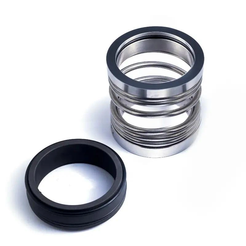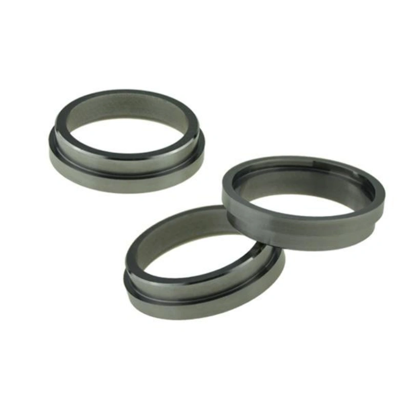
During operation, mechanical seals not only require control of the temperature and lubrication conditions at the sealing faces but may also face issues such as crystallization, coking, solidification, or deposition following medium leakage.
Mechanical Seal Quench is an auxiliary measure applied to the atmospheric side of the seal. By introducing media such as water, steam, or nitrogen, it helps control the local environment, reduce the formation of deposits, and protect seal-related components.
This article will introduce the function of mechanical seal quenching, the flow paths of the media, and applicable operating conditions, with a focus on analyzing the selection criteria for water, steam, and nitrogen. It aims to help you develop a safe and reliable mechanical seal quenching solution.
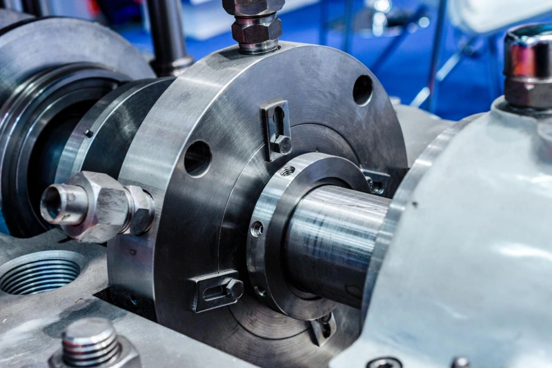
Mechanical Seal Quench involves introducing an auxiliary medium from the outside. It enters the atmospheric side of the mechanical seal. Commonly used media include steam, purified water, or nitrogen. Its purpose is to improve the operating environment on the outside of the seal.
When pumping media prone to crystallization, salt precipitation, or solidification, even a small amount of leakage can form solids on the atmospheric side. Rapidly cooling the medium can help flush away these substances or alter the local environment, thereby reducing deposit buildup.
In certain high-temperature hydrocarbon applications, leaked media may form coke deposits upon contact with air. Using appropriate steam or nitrogen can minimize air exposure and reduce the risk of coking.
Although the term “quench” is included in the name, it is not necessarily used for cooling. Depending on the medium and operating conditions, a quench system can provide cooling, provide heating via steam, or use nitrogen to reduce icing issues around low-temperature seals. Therefore, one cannot simply assume that all quench systems should use cold water.
Quenching can reduce the accumulation of harmful substances on the outside of the seal, keeping the relevant areas relatively clean and thereby lowering the risk of operational failures caused by crystallization, coking, or icing.
| Operating Condition | Possible Problem | Main Quench Function |
|---|---|---|
| High-Temperature Hydrocarbons | Coking and oxidation on the atmospheric side. | Reduces coking and deposits. |
| Crystallizing Fluids | Crystal buildup and component sticking. | Reduces crystallization and removes deposits. |
| Low-Temperature / Cryogenic Fluids | Moisture condensation and icing. | Reduces icing risk. |
| Solidifying Fluids | Leakage solidifies after cooling. | Reduces buildup through heating or cleaning. |
Tip: The core benefit of rapid cooling for mechanical seals is to improve the operating environment on the atmospheric side of the seal, not to replace the mechanical seal itself. When your operating conditions pose a risk of coking, crystallization, solidification, or freezing, a properly designed rapid cooling system can help improve the reliability of the seal’s operation.
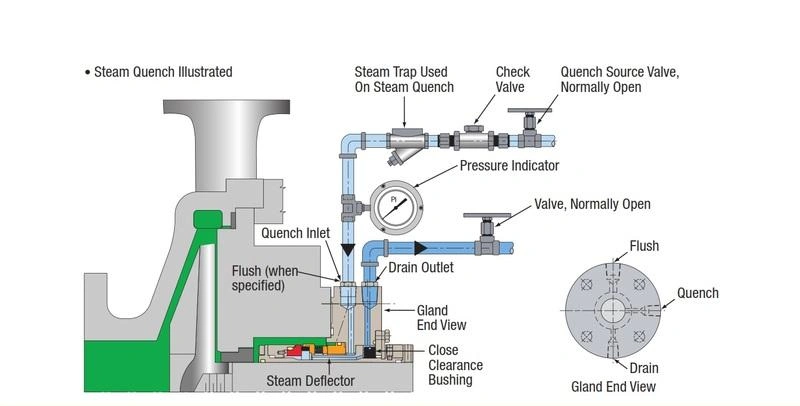
The key to mechanical seal quenching is to allow an external auxiliary medium to flow through the atmospheric side of the mechanical seal.
You can divide a mechanical seal into two zones: the process side, which is in contact with the medium inside the pump, and the atmospheric side, which is exposed to the external environment. These two zones are separated by the seal faces, which consist of a rotating ring and a stationary ring.
In a typical API Plan 62 quench configuration, the auxiliary medium enters from an external supply system. It flows toward the quench inlet on the seal gland. It passes through the space near the outer side of the seal faces. Finally, it is discharged through the drain outlet.
Under normal design conditions, the quench medium should not be considered part of the fluid supplied to the pump. It primarily remains on the atmospheric side of the mechanical seal and does not need to pass through the sealing faces into the seal chamber.
Tip: If you observe abnormal ingress of the quench medium into the pump, or if a large volume flows into the bearing area, you must inspect the seal configuration, pressure conditions, and piping layout; this phenomenon should not be considered normal operation.
During an actual inspection, you should focus on verifying the following aspects.
| Check Item | How to Verify |
|---|---|
| Quench Inlet | Confirm connection to the seal gland Quench port, not the Flush port. |
| Flow Area | Confirm the medium reaches the atmospheric side of the seal. |
| Drain Outlet | Keep the drain open for liquid and condensate discharge. |
| Throttle Bushing | Verify it matches the seal design and limits excessive quench loss. |
| Supply Pressure | Follow manufacturer limits to avoid excess pressure or backflow. |
| Flow Condition | Check for closed valves, blockage, or abnormal liquid buildup. |
Tip: The flow and discharge methods for steam, water, and nitrogen may differ. In particular, when rapidly cooling steam, you must also consider whether condensate can be drained in a timely manner to minimize the accumulation of condensate near high-temperature seals, where it could re-vaporize and cause adverse effects.
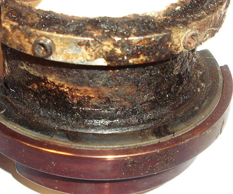
Not all mechanical seals require quenching. Whether quenching is necessary depends primarily on the properties of the process medium, the operating temperature, and whether the leaking medium will cause coking, crystallization, solidification, or freezing upon contact with air.
Leakage coming into contact with air can easily form hard carbon deposits that impede the movement of sealing components.
In such cases, Steam Quench may be considered to use steam to improve the environment on the atmospheric side of the seal, thereby reducing coking and the accumulation of deposits.
If you are handling solutions prone to crystallization—such as certain salt solutions or alkaline solutions—leaking fluid on the atmospheric side may form crystals due to water evaporation, increased concentration, or temperature changes.
Consider using a “Clean Water Quench” to help dissolve or flush away deposits.
Tip: Direct water quenching should not be used if the process medium reacts dangerously with water or is more likely to solidify or precipitate solids upon contact with water.
In cryogenic service, extremely low temperatures on the outer side of the mechanical seal may cause moisture in the air to condense and freeze.
Ice buildup may impede the movement of seal components or obstruct the discharge passage. Consider using a dry nitrogen quench to reduce the ingress of moist air into the area outside the seal, thereby lowering the risk of icing.
The fluid solidifies or polymerizes as it cools after leaving the pump housing. Depending on its properties, water, steam, or other compatible rapid-cooling media may be selected. however, if the problem stems from insufficient lubrication within the seal chamber or on the seal faces, rapid cooling from the atmospheric side alone will not resolve the issue.
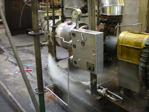
When selecting a mechanical seal quench fluid, you cannot simply assume that water is the cheapest, steam is suitable for high temperatures, and nitrogen is the safest.
The correct approach is to first understand the properties of the process medium, then determine what issues need to be addressed on the seal’s atmosphere side, and finally confirm whether the quench fluid is compatible.
| Check Item | How to Verify |
|---|---|
| Quench Inlet | Confirm connection to the seal gland Quench port, not the Flush port. |
| Flow Area | Confirm the medium reaches the atmospheric side of the seal. |
| Drain Outlet | Keep the drain open for liquid and condensate discharge. |
| Throttle Bushing | Verify it matches the seal design and limits excessive quench loss. |
| Supply Pressure | Follow manufacturer limits to avoid excess pressure or backflow. |
| Flow Condition | Check for closed valves, blockage, or abnormal liquid buildup. |
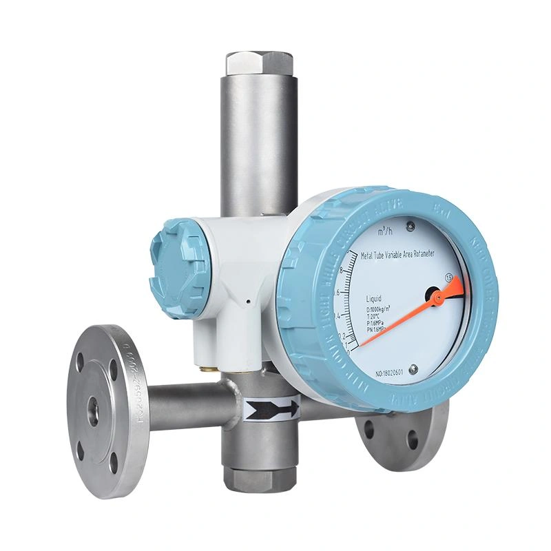
Whether a mechanical seal quench system operates properly depends not only on whether you choose water, steam, or nitrogen, but also on whether the flow, pressure, temperature, and compatibility meet the requirements.
Flow rate refers to the volume of medium flowing through the quenching pipeline per unit of time.
If the flow rate is insufficient, the quenching medium may not effectively remove crystallites, reduce coking, or maintain the required conditions. An excessive supply may increase medium consumption and the burden on the discharge system.
When selecting the appropriate system, you should consider the type of quenching medium, the rate of deposit formation, pipeline resistance, and discharge capacity.
Pressure is a critical control parameter in the quench system. Unlike the flushing system, which supplies fluid to the seal chamber, the typical Plan 62 quench system operates in an area close to atmospheric pressure and therefore uses a low-pressure supply.
You must implement appropriate pressure-reduction, regulation, and monitoring measures based on the seal configuration and ensure that the vent lines remain unobstructed.
Temperature not only affects the effectiveness of rapid cooling but may also impact the service life of sealing materials and the stability of the process medium.
In low-temperature operating conditions, dry nitrogen can reduce the ingress of moisture from the air into the outer side of the seal, thereby lowering the risk of icing. However, the supply gas temperature and dryness must still meet the equipment’s design requirements.
Therefore, you cannot determine the rapid cooling temperature based solely on the process temperature inside the pump; instead, you must also consider the environment on the atmospheric side of the seal, the properties of the rapid cooling medium, and the permissible temperature range of the sealing materials.
Compatibility refers to whether the quenching medium can safely coexist with the process medium and sealing materials without causing adverse chemical reactions, corrosion, or changes in material properties.
When assessing compatibility, one must not rely solely on the names of the media; temperature, concentration, contact time, and actual operating conditions must also be taken into account.
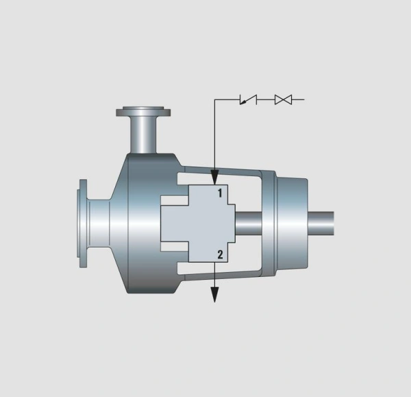
In mechanical seal systems, API Plan 62 is a common quench configuration, but it is not the only auxiliary piping scheme related to the atmospheric side of the seal. You may also encounter Plan 51, Plan 61, Plan 65A, and Plan 65B. Although these schemes all relate to the outside of the seal, their functions are not entirely the same.
| API Plan | Main Function | How It Works | Typical Use | Key Notes |
|---|---|---|---|---|
| Plan 62 | Prevents coking, crystallization, and icing. | Water, steam, or nitrogen flows through the atmospheric side and drains out. | Hot hydrocarbons, crystallizing fluids, and some cryogenic services. | Control pressure and flow; keep drains open. It does not stop seal leakage. |
| Plan 61 | Provides connections for future quench use. | Quench and drain ports are provided without continuous fluid supply. | Applications that may need quench later. | Unused ports must be correctly plugged. |
| Plan 51 | Provides a liquid quench from a reservoir. | A reservoir supplies liquid to the atmospheric side without continuous external flow. | Specific vertical pump or anti-icing applications. | Monitor liquid level and fluid compatibility. |
| Plan 65A | Detects excessive liquid leakage. | Leakage is restricted, collected, and triggers a level alarm. | Single seals requiring rapid leak detection. | Keep the drain path open and verify the alarm. |
| Plan 65B | Collects and monitors leakage. | Leakage accumulates in a collection vessel for level monitoring. | Single seals requiring accumulated leakage monitoring. | Drain regularly and inspect the monitoring system. |
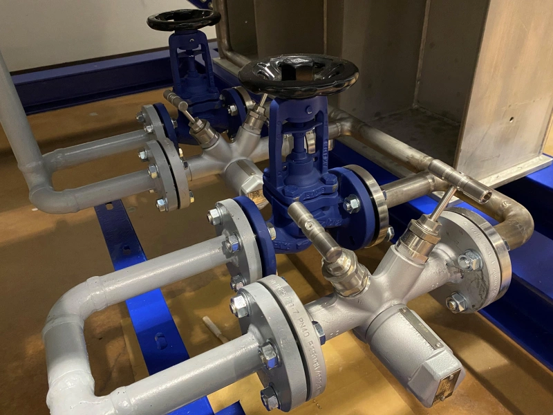
A mechanical seal quench system requires not only the selection of an appropriate quench medium but also the proper design of piping, connections, and monitoring measures. Even when using clean water, steam, or nitrogen, the quench may fail to function as intended if the piping becomes blocked, connections are incorrect, or drainage is inadequate.
Quench piping includes supply lines, control valves, necessary check valves, and discharge lines. The actual configuration should be determined based on the type of medium and the mechanical seal manufacturer’s piping diagram.
Supply lines should minimize unnecessary bends and resistance to prevent the quench medium from failing to reach the seal due to blockages or pressure loss.
Tip: If the discharge line is connected to a recovery system, you must also ensure that the system does not generate impermissible back pressure and does not discharge hazardous media directly into areas where personnel are present.
There may be multiple connection points on the mechanical seal gland; you need to distinguish between the following three common markings.
| Port Marking | Name | Main Function |
|---|---|---|
| Q | Quench | Introduces quench fluid to the atmospheric side of the seal. |
| D | Drain | Drains quench fluid, condensate, or leakage. |
| F | Flush | Supplies flush or circulation fluid to the process side. |
Just because the interface dimensions are the same doesn’t mean they are interchangeable. Quench and Flush serve different functions; connecting them incorrectly may result in quench failure or even create pressure and flow conditions that do not conform to the design specifications.
A quenching system does not necessarily require complex automatic control equipment, but you should at least be able to determine whether the supply is normal, whether the discharge is unobstructed, and whether there are any abnormal leaks.
Common monitoring methods include the following.
| Monitoring Item | What to Check | Possible Issue |
|---|---|---|
| Pressure | Quench supply pressure matches design requirements. | Supply problem, regulator failure, or blocked line. |
| Flow | Quench flow is sufficient and stable. | Closed valve, low supply, or blockage. |
| Temperature | Quench medium and local temperatures are within limits. | Abnormal supply temperature, condensation, or insufficient heating. |
| Drain | Drain path is clear with no abnormal liquid buildup. | Blocked drain, condensate buildup, or abnormal leakage. |
| Leakage | Check for abnormal leakage on the atmospheric side. | Seal degradation or auxiliary system problem. |
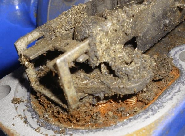
During operation, mechanical seal quenching systems may experience issues such as insufficient flow, abnormal pressure, blocked discharge, improper temperature, or incompatibility of the quenching medium.
| Common Problem | Possible Cause | Warning Signs | Recommended Check |
|---|---|---|---|
| Insufficient Quench Flow | Low supply, closed valve, or blocked line. | Low flow, more deposits, abnormal temperature. | Check valves, piping, and actual flow. Do not rely on pressure alone. |
| Excessive Quench Pressure | Regulator failure, poor adjustment, or blocked drain. | High pressure, fluid escape, increased discharge. | Check regulator, control valve, and drain line. |
| Blocked Drain / Condensate Buildup | Crystals, coke, debris, or poor condensate drainage. | Reduced drainage, liquid buildup, abnormal noise or leakage. | Check drain path and steam trap. |
| Wrong Quench Fluid / Temperature | Incompatible fluid, poor water quality, or incorrect temperature. | Corrosion, scaling, icing, or material damage. | Verify fluid quality, temperature, and material compatibility. |
| Abnormal Seal Leakage | Seal wear, deposits, installation, or operating issues. | Increasing leakage or changes in discharge condition. | Separate quench fluid from process leakage and inspect the seal condition. |
Tip: The warning signs listed above are for preliminary assessment only; the cause of a malfunction should not be determined based on a single symptom. When troubleshooting, it is recommended to follow this sequence: “Check the supply first, then check the discharge, and finally evaluate the seal itself.”
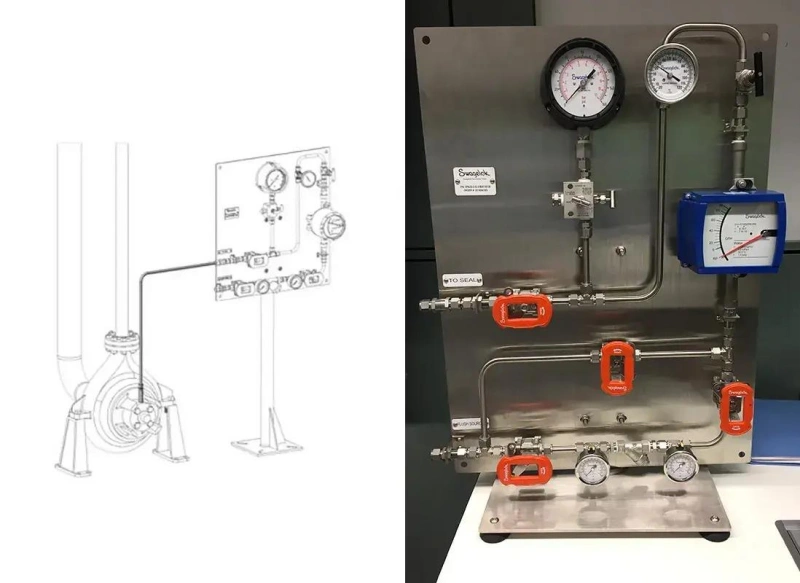
To design a reliable mechanical seal quench system, you cannot simply decide whether to use water, steam, or nitrogen; you must also comprehensively consider the properties of the process medium, the seal configuration, supply conditions, piping layout, and monitoring requirements.
First, you need to collect basic operating information about the pump, including the name of the process medium, its chemical composition, concentration, operating temperature, seal chamber pressure, and start-up and shutdown conditions.
It is particularly important to determine whether the leaking medium is prone to crystallization, coking, oxidation, or solidification upon contact with air.
Once the operating conditions have been determined, you need to select a quench fluid based on the actual risks.
For media prone to forming water-soluble crystals, consider using a clean water quench to help dissolve or remove deposits. For certain high-temperature hydrocarbon media, consider a steam quench to reduce oxidation and coking.
Tip: You should not base your decision solely on the name of the medium; you must also check for chemical compatibility—that is, whether the quench fluid will react adversely with the process medium, seals, metal materials, or other components.
During operation, mechanical seal quenching systems may experience issues such as insufficient flow, abnormal pressure, blocked discharge, improper temperature, or incompatibility of the quenching medium.
Not all mechanical seals can be directly equipped with a quench system. You need to check whether the seal gland has a quench inlet and drain outlet, and confirm that the internal flow path can direct the quench medium to the correct location.
Once the quench medium has been selected, you need to specify the flow rate, supply pressure, and supply temperature.
The flow rate must meet the actual requirements for cleaning, preventing deposits, or temperature control, but “more is not necessarily better.” The pressure should also comply with low-pressure quench design specifications to prevent abnormal leakage of the quench medium or its entry into areas where it should not be present.
A reliable quench system must ensure a stable supply, unobstructed discharge, and the ability to detect abnormalities in a timely manner.
You should verify that the supply valves, necessary check valves, pressure regulating equipment, and discharge piping comply with the design specifications. For steam systems, you must also consider condensate drainage and drain measures based on the piping design.
Tip: You should also clearly define inspection intervals, piping cleaning requirements, instrument calibration, and procedures for handling abnormalities. Do not wait until a seal shows obvious signs of leakage before checking whether the quench system is functioning properly.
A certain supply pressure is required, but it is a low-pressure system. The specific pressure depends on the seal design, the quench medium, and the manufacturer’s requirements; therefore, a fixed value cannot be universally applied. Excessive pressure may cause abnormal leakage of the medium or its ingress into the bearing area.
The quench fluid primarily acts on the atmospheric side of a single-face seal to prevent crystallization, coking, or freezing. The buffer fluid is used between the faces of a double-face seal, such as in API Plan 52, and is primarily used for lubrication, cooling, and to collect leakage from the inner seal; its pressure is typically lower than the pressure in the seal chamber.
Yes, but the water quality and compatibility with the medium must be verified. Impurities and hardness components in plant water may cause scaling, clogging, or corrosion. Clean water that meets the requirements should be used based on operating conditions, and treated water should be used when necessary.
Steam is commonly used in some high-temperature hydrocarbon applications. It reduces contact between air and the leaking medium, lowering the risk of oxidation and coking, while also helping to prevent the leaked material from cooling and solidifying. When using steam, ensure that condensate can be properly drained.
There is no universal standard for flow rate. The specific flow rate depends on the quench medium, seal design, and operating conditions. You should determine the flow rate based on the manufacturer’s specifications to ensure that deposit prevention or temperature control requirements are met—rather than assuming that a higher flow rate is always better.
It is possible. A blocked line may cause crystallization, coking, or liquid accumulation on the outer surface of the seal, increasing the risk of component seizure and seal failure. However, a blockage does not necessarily lead to immediate failure; supply and discharge lines should be inspected promptly.
This depends on the composition and hazardous nature of the discharge. Even when using clean water for quenching, the discharge may be contaminated with process media. The appropriate method of discharge or recovery should be selected based on environmental and safety requirements; hazardous media must not be discharged directly into standard floor drains.
You can check the supply pressure, actual flow rate, temperature, and discharge status, and observe whether there is crystallization, coking, or abnormal leakage on the outside of the seal. Do not assume that quenching is effective simply because the pressure is normal, and do not touch high-temperature or low-temperature piping directly.
Overall, mechanical seal quenching is an important auxiliary measure for improving the operational reliability of mechanical seals. Whether it’s preventing crystallization, reducing coking, controlling temperature, or lowering the risk of freezing, the key lies in selecting the appropriate quenching medium and configuration based on actual operating conditions.
When designing a quenching system, you need to comprehensively consider the properties of the process medium, the seal design, flow rate, pressure, temperature, and material compatibility.
If you are looking for reliable mechanical seals and supporting solutions, please contact Sakowitz to discuss your specific operating conditions, technical requirements, and selection needs in further detail.
—— We Will Provide You With Professional OEM Solutions.
Whether you require pump bearings, pump valves, mechanical seals, or other custom-engineered components, we support production based on your drawings as well as rapid prototyping.
Please complete the form on the right and upload your technical drawings or specifications. Our engineering team will review your requirements within 24 hours and provide a detailed quotation, application recommendations, and delivery schedule.
Copyright © 2025 Sakowit, All rights reserved.
WhatsApp us